Front panel features, Input and output buttons, S -2 – Extron Electronics ISM 824 User Manual
Page 34: Operation and setup
ISM 824 Integration Scaling Multiswitcher • Operation and Setup
3-2
Operation and Setup
Operation and Setup
Front Panel Features
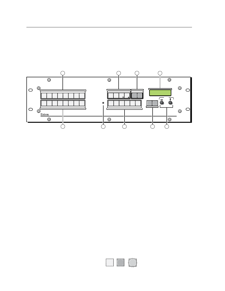
All of the ISM 824’s controls and indicators are on the front panel (figure 3-1). Input
and output selection buttons are located on the left, with control and adjustment
buttons, encoders, and an LCD screen towards the right. A 2.5 mm configuration
port is located to the left of the picture adjustment buttons.
All buttons are backlit (green, red, or amber) and can be relabeled as desired.
Chapter 5, “Replacing the button labels” section.
Figure 3-1 — ISM 824 Integration Scaling Multiswitcher front panel
features
Input and output buttons
a
Input selection buttons — The Input 1 through Input 8 buttons select and
identify the associated input to tie to any selected output(s)
When an input button is lit green, it indicates a video input selection. When
it is lit red it indicates an audio input selection, and when lit amber the input
selection is both video and audio. Inputs can be tied to any output, as video,
See the “ Front Panel Operation”, “Making input to output
section later in this chapter for the method.
Input buttons are also used to save and recall presets (1 to 8).
Panel Operation”, “Saving a preset”
and
this chapter for the method.
b
Output selection buttons — The output buttons 1 through 8 select the
output to tie any selected active input, and for identifying any existing ties
(video, audio, or both) active on that selected output.
section later in this chapter for the method.
When an output button is lit green, it indicates a video output is selected. If
the button is lit red it indicates an audio output selection. If the button is
lit amber, then both video and audio outputs are indicated. Outputs can be
tied to any input, as video, audio, or both.
See the “ Front Panel Operation”,
“Making input to output ties” section
later in this chapter for method.
Output buttons are also used to save and recall presets (9 to 16). See the
”Front Panel Operation”, “Saving a preset”
later in this chapter for method.
N
Throughout this manual the front panel buttons status (unlit, lit, or flashing) is
shown as:
Unlit
Flashing
Lit
AUDIO
VIDEO
IO
CONTROL
ENTER
PRESET
VIEW
ESC
AUDIO
VIDEO
I/O
CONTROL
ENTER
PRESET
VIEW
ESC
INPUTS
1 2 3 4 5 6 7 8
7 8
1 2 3 4 5 6
OUTPUTS
PICTURE ADJUSTMENTS
INTEGRATION SCALING MULTISWITCHER
ISM 824
COLOR/
TINT
BRIGHT/
CONT
DETAIL
POSITION
SIZE
ZOOM
MENU
NEXT
ADJUST
CONFIG
2
1
5
3
4
6
7
9
8
ISM 824
V
ers
i
On
1.00