Installing the optional output cards, Installing the optional output boards – Extron Electronics ISM 824 User Manual
Page 31
2-9
ISM 824 Integration Scaling Multiswitcher • Installation
Installing the optional output boards
If the optional boards are already installed in the ISM 824, connect suitable display
devices and configure the input and outputs as applicable.
for front panel operation. Also see
chapter 5, “ISM 824 Multiswitcher Software”,
and
for alternative methods in configuring the
multiswitcher.
If the boards are not pre-installed, install the board following the steps below:
1
.
Turn off the ISM 824, and remove the power cord. Repeat for all connected
devices.
2
.
Remove the blank from the rear output port where the board is to be inserted.
To do this, loosen and remove the two retaining screws (top and bottom), and
lift the blank away.
N
Re-use the screws to secure the new output board in place. Retain the blanks for
future use.
Before installing Dual output wideband boards, refer to
for information on output port configuration for that
specific board type.
3.
Remove the board from its outer box and, holding the boards by the rear
frame or BNC connectors, remove the board from the anti-ESD bag, taking
care not to touch any of the components on the board.
4.
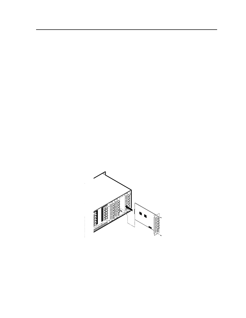
With the board upright, align the front (non connector end) of the board with
the top and bottom plastic guides in the ISM 824 (see figure 2-11). Slide the
board in carefully, ensuring that it remains within the guides, and push it
home firmly.
100
- 24
0
50/60 Hz
1.2
A M
AX
.
1
2
3
4
5
6
7
8
2
1
2
3
4
5
6
7
8
1
2
1
INP
UT
S
PAS
S-T
HR
U
R/R-
Y
G/Y
VID
B/C
B-Y
H/HV
V
R/R-
Y
G/Y
VID
B/C
B-Y
H/HV
V
PA
SS
TH
RU
INP
UT
S
RE
SE
T
LA
N
R
E
M
O
TE
RS232/RS42
2
A
C
T
LINK
OUTP
UT
VID
EO
SC
AL
ER
70-5
45-0
1
3
R/
R-Y
G/Y
B/
B-Y
H/
HV
V
OUTP
UT
UN
IV.
SC
AL
ER
70-5
44-0
1
4
R/
R-Y
G/Y
B/
B-Y
H/
HV
V
OUTP
UT
PA
SS
TH
RU
70-5
47-0
1
6
R/
R-Y
G/Y
B/
B-Y
H/
HV
V
Extron
ISM 824
Integration Scaling
Matrix Switcher
Align Output Card
with top & bottom
plastic guides.
R/
R-Y
G/Y
B/
B-Y
H/
HV
V
OUTP
UT
5
SC
AN
CO
NV
.
70-5
46-0
1
Figure 2-11 — Optional output board installation
5
.
Using the two screws retained from removing the blank, secure the board in
place.
6
.
If applicable, repeat for any other output boards.
7.
Connect and power up the ISM 824. If the board has been installed correctly,
the device recognizes the new output board, and the LCD displays the board
number, type, and output number, and a 30 second countdown timer. The
given output number is used to tie inputs .
N
If an ISM RGB board is installed, during power up a color bar test briefly
appears on the display device and remains visible for 30 seconds.