Optional output card connections, Video output connections, Audio output connections – Extron Electronics ISM 824 User Manual
Page 30: Optional output card connections -8, Connections -8, Installation, cont’d, Optional output board connections
Installation, cont’d
ISM 824 Integration Scaling Multiswitcher • Installation
2-8
Optional output board connections
Video output connections
i
There are different output board options available, for the four expansion slots
at the rear of the ISM 824. Figure 2-2 shows the following four:
ê
ISM VS (Video Scaler) — Connect RGB video displays to this set of
5 female BNC connectors to output scaled or unprocessed signals
(RGBHV, RGBS, RGsB, or HD component (YUV) video).
ë
ISM 2WB (Dual wideband) — Connect RGB video, component/HDTV
video, S-Video, or composite video displays, as applicable, or other
devices to these 15-pin HD connectors for each output.
N
For the installation configuration shown in figure 2-2, the top 15-HD pin
connector is output 5, and the lower 15-pin HD connector is output 6.
í
ISM DVI (Universal scaler with DVI output) — Connect a suitable
display to this single link DVI-D connector to output scaled computer
video rates up to 1920 x 1200 and HDTV rates at 720p, 1080i, and
1080p/60.
ì
ISM RGB (Universal Scaler) — Connect RGB video displays to this set
of 5 female BNC connectors to output scaled signals (RGBHV, RGBS,
RGsB, or HD component (YUV) video).
Other optional output board types are:
ISM HDSDI
(Universal scaler with HDSDI output) — Connect a suitable
display to this single link HD-SDI connector to output any of five
selectable SMTPE and ITU compliant video output rates including
720p 24/25/30/50/59.94/60, 1080i 50/59.94/60, and 1080p/24/25/30.
ISM 1WB (Single wideband) —
Connect an RGB video, component/
HDTV video, S-Video, or composite video display to this set of 5 female
BNC connectors to output unprocessed video signals.
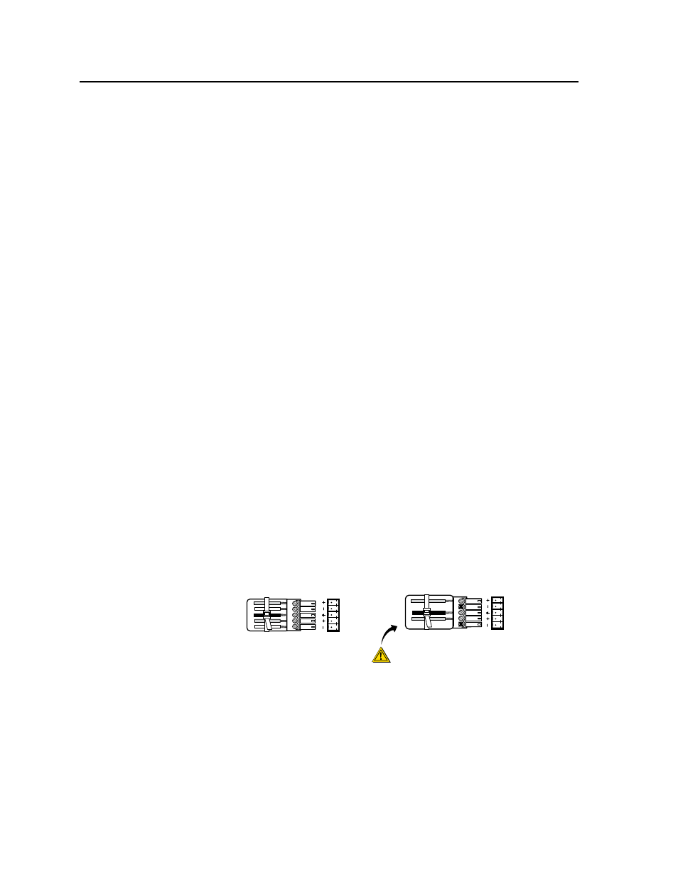
Audio output connections
Audio output connectors —
Connect audio devices, such as an audio
amplifier or powered speakers to the 3.5 mm, 5-pole captive screw connectors
on the board. The connectors output the selected unamplified line level
audio. See figure 2-10 to properly wire an output connector.
Unbalanced Stereo Output
Tip
NO GROUND HERE.
Sleeve(s)
Tip
NO GROUND HERE.
Balanced Stereo Output
Tip
Ring
Sleeve(s)
Tip
Ring
L
R
L
R
Left
Right
Left
Right
CAUTION
For unbalanced audio, connect the sleeve(s)
to the center contact ground.
DO NOT
connect the sleeve(s) to the negative (-)
Figure 2-10 — Captive screw connector wiring for audio output