7 powerup reset sequence, 4 boot mode, 150 supported strap combinations – Intel NETWORK PROCESSOR IXP2800 User Manual
Page 370
370
Hardware Reference Manual
Intel
®
IXP2800 Network Processor
Clocks and Reset
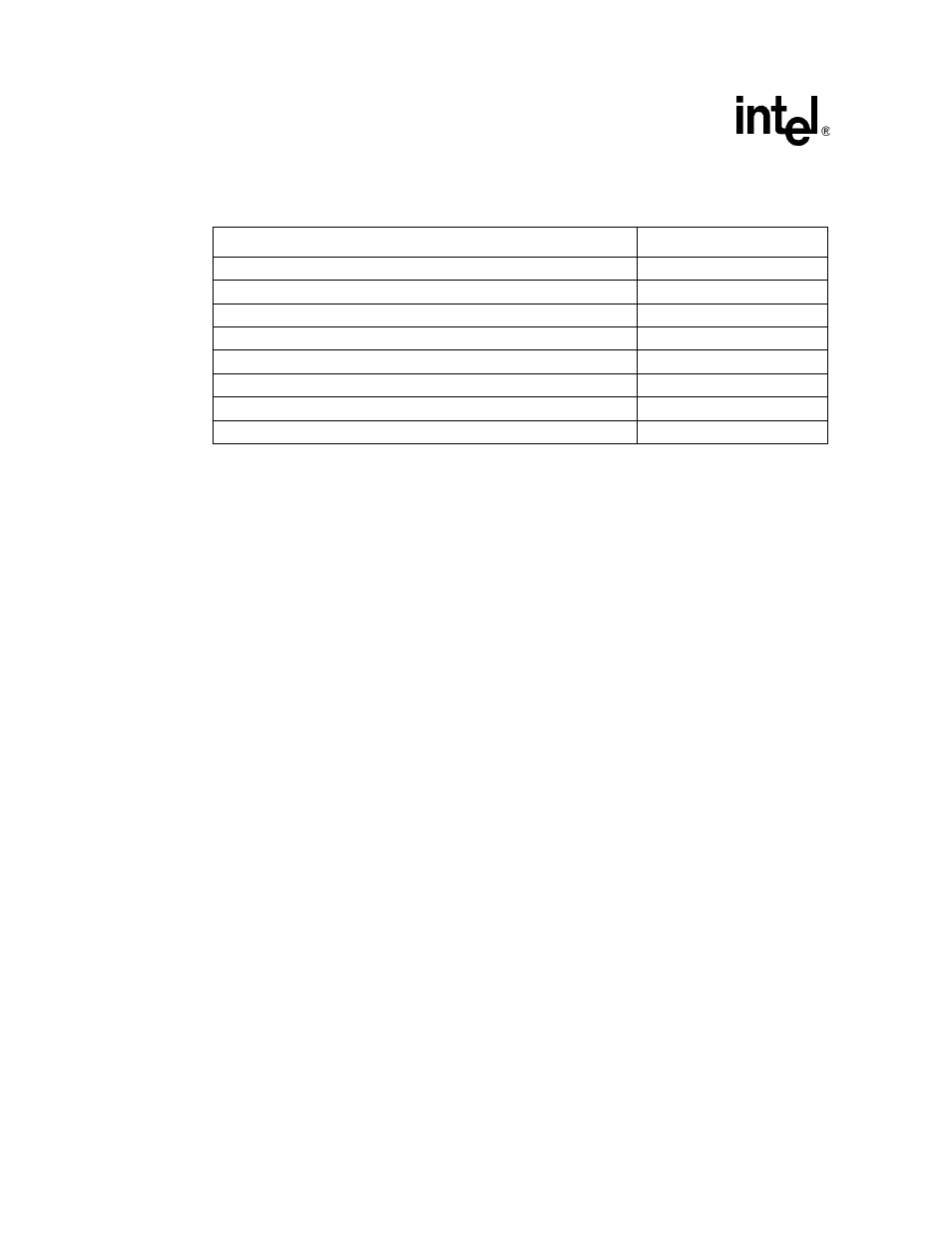
lists the supported Strap combinations of CFG_PROM_BOOT, CFG_RST_DIR, and
CFG_PCI_BOOT_HIST.
One more restriction in the PCI unit is that, if the IXP2800 Network Processor is a PCI_HOST or
PCI_ARBITER, it should also be PCI_CENTRAL_FUNCTION.
10.3.7
Powerup Reset Sequence
When the system is powered up, bypass clock is sent to all the units as the chip begins to power up.
It will merely be used to allow a gradual power up and to begin clocking state elements to remove
possible circuit contention. When PLL gets locked after nRESET is de-asserted, it will start
generating divide_by_16 clocks for all the units. Reset from the IXP_RESET register is also
removed at the same time. When software updates the clock count register, clocks are again
stopped for 32 cycles and then start again.
The reset sequence described above is the same in the case when reset happens through the
PCI_RST_L signal and CFG_RST_DIR is asserted.
Once in operation, if watchdog timer expires with watchdog timer enable bit (bit [0] in the Timer
Watchdog Enable register ON, a reset pulse from the watchdog timer logic resets the IXP_RESETn
registers and in turn causes the entire network processor to be reset.
10.4
Boot Mode
The IXP2800 can boot in following two modes:
•
Flash ROM
•
PCI Host Download
shows the IXP2800 Network Processor Boot process.
Table 150. Supported Strap Combinations
CFG_PROM_BOOT, CFG_RST_DIR, CFG_PCI_BOOT_HOST
Result
000
Allowed
001
Allowed
010
Not allowed
011
Not allowed
100
Allowed
101
Allowed
110
Allowed
111
Allowed