1 spi-4, Spi-4, D in – Intel NETWORK PROCESSOR IXP2800 User Manual
Page 250: Section 8.2.2.1
250
Hardware Reference Manual
Intel
®
IXP2800 Network Processor
Media and Switch Fabric Interface
The
src_op_1
and
src_op_2
operands are added together to form the address in RBUF (note that
the base address of the RBUF is 0x2000). The
ref_cnt
operand is the number of 32-bit words or
word pairs, that are pushed into two sequential S_TRANSFER_IN registers, starting with
$s_xfer_reg
.
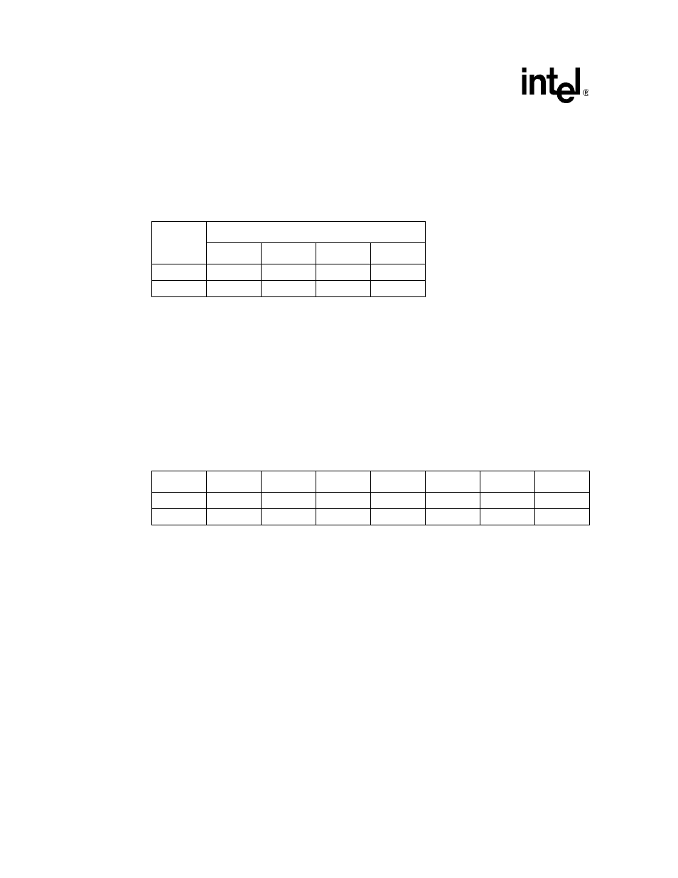
above, reading eight bytes from offset 0 into transfer registers
0 and 1 would yield the result in
Microengine can move data from RBUF to DRAM using the instruction:
dram[rbuf_rd, --, src_op1, src_op2, ref_cnt], indirect_ref
The
src_op_1
and
src_op_2
operands are added together to form the address in DRAM, so the
dram
instruction must use the
indirect_ref
modifier to specify the RBUF address (refer to the
IXP2800 Network Processor chassis chapter for details). The
ref_cnt
operand is the number of
64-bit words that are read from RBUF.
above, reading 16 bytes from offset 0 in RBUF into DRAM
would yield the result in
in DRAM (addresses in DRAM must be aligned to
8-byte units. The data from lower-offset RBUF offsets goes into lower addresses in DRAM.)
For both types of RBUF read, reading an element does not modify any RBUF data, and does not
free the element, so buffered data can be read as many times as desired.
8.2.2.1
SPI-4
SPI-4 data is placed into RBUF as follows:
•
At chip reset all elements are marked invalid (available).
•
When a SPI-4 Control Word is received (i.e., when RCTL is asserted) it is placed in a
temporary holding register. The Checksum accumulator is cleared. The subsequent action is
based on the Type field.
— If Type is Idle or Training, the Control Word is discarded.
— If Type is not Idle or Training:
An available RBUF element is allocated by receive control logic.(If there is no available
element, the data is discarded and MSF_Interrupt_Status[RBUF_Overflow is set.) Note
that this normally should not happen because, when the number of RBUF elements falls
below a programmed limit, the flow control status is sent back to the PHY device (refer to
Example 34. Data from RBUF Moved to Microengine Transfer Registers
Transfer
Register
Number
Bit Number within Transfer Register
31
24 23
16 15
8 7
0
0
0
1
2
3
1
4
5
6
7
Example 35. Data from RBUF Moved to DRAM
63
56 55
48 47
40 39
32 31
24 23
16 15
8 7
0
4
5
6
7
0
1
2
3
C
D
E
F
8
9
A
B