Dte and dce mode – Maxim Integrated DS33Z41 User Manual
Page 43
DS33Z41 Quad IMUX Ethernet Mapper
43 of 167
• MII error asserted during the reception of the frame.
• Dribbling bits occurred in the frame.
• CRC error occurred.
• Length error occurred—the length indicated by the frame length is inconsistent with the number of bytes
received.
• Control frame was received. The mode must be full duplex.
• Unsupported control frame was received.
Note that frames received that are runt frames or frames with collision will automatically be rejected.
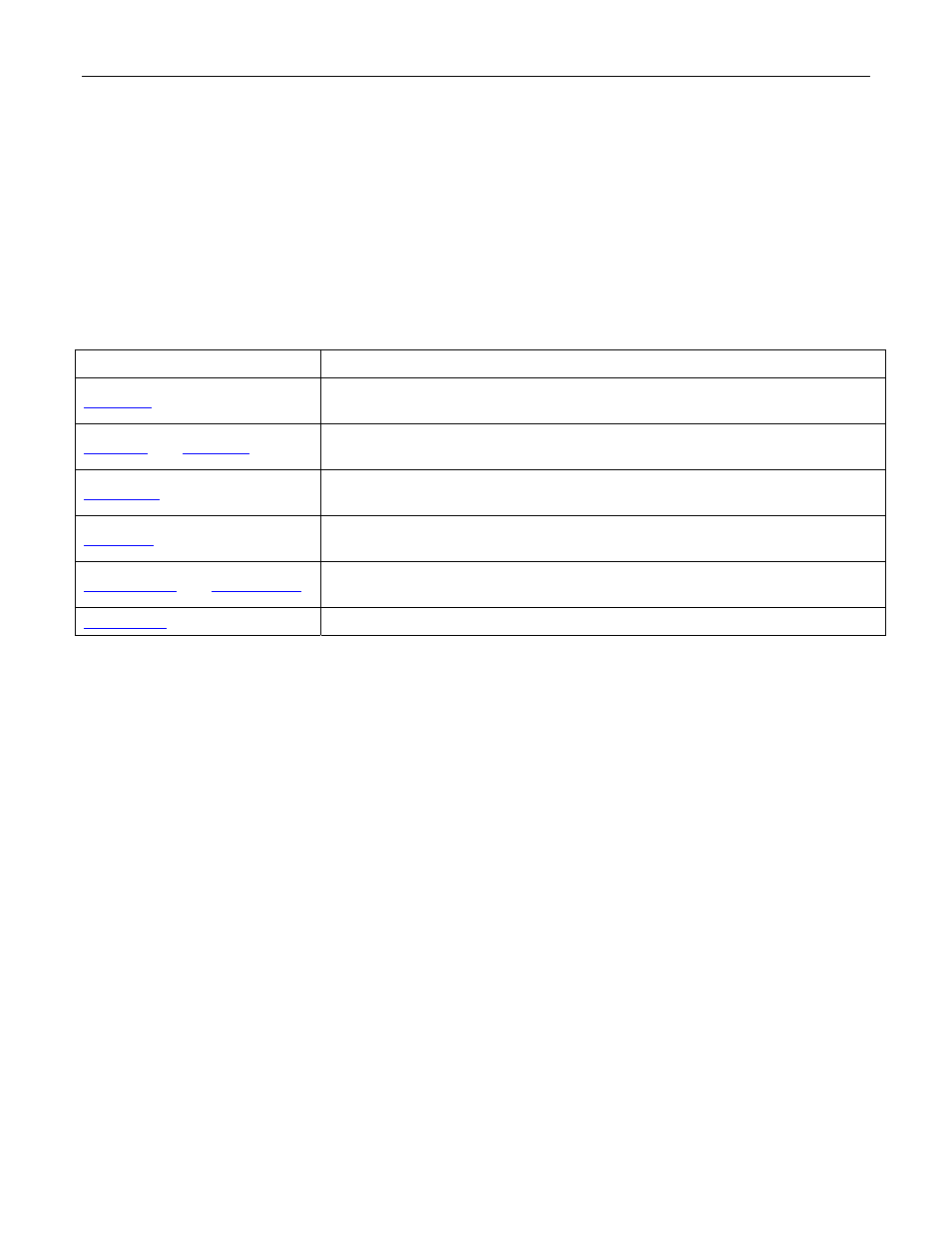
Table 8-7. Registers Related to the Ethernet Port
REGISTER FUNCTION
SU.TFRC
This register determines if the current frame is retransmitted due to various
transmit errors
SU.TFSL
and
SU.TFSH
These 2 registers provide the real time status of the transmit frame. Only apply
to the last frame transmitted.
SU.RFSB0
to 3
These registers provide the real time status for the received frame. Only apply
to the last frame received.
SU.RFRC
This register provides settings for reception or rejection of frame based on
errors detected by the MAC.
SU.RMFSRH
and
SU.RMFSRL
The settings for this register provide the maximum size of frames to be
accepted from the MII/RMII receive interface.
SU.MACCR
This register provides configuration control for the MAC
8.13.1 DTE and DCE Mode
The Ethernet MII/RMII port can be configured for DCE or DTE Mode. When the port is configured for the DTE
Mode it can be connected to an Ethernet PHY. In DCE mode, the port can be connected to MII/RMII MAC devices
other than an Ethernet PHY. The DTE/DCE connections for the DS33Z41 in MII mode are shown in the following
two figures.
In DCE Mode, the DS33Z41 transmitter is connected to an external receiver and DS33Z41 receiver is connected
to an external MAC transmitter. The selection of DTE or DCE mode is done by the hardware pin DCEDTES.