Maxim Integrated DS33Z41 User Manual
Page 17
DS33Z41 Quad IMUX Ethernet Mapper
17 of 167
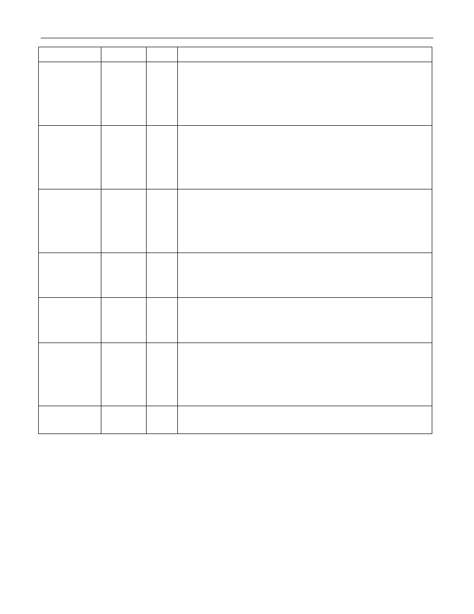
NAME PIN
TYPE
FUNCTION
RD/DS
E1 I
Read Data Strobe (Intel Mode). The DS33Z41 drives the data bus
(D0-D7) with the contents of the addressed register while
RD and CS
are both low.
Data Strobe (Motorola Mode). Used to latch data through the
microprocessor interface.
DS must be low during read and write
operations.
WR/RW
E2 I
Write (Intel Mode). The DS33Z41 captures the contents of the data
bus (D0:D7) on the rising edge of
WR and writes them to the addressed
register location.
CS must be held low during write operations.
Read Write (Motorola Mode). Used to indicate read or write
operation. R
W must be set high for a register read cycle and low for a
register write cycle.
INT
F3 OZ
Interrupt Output. Outputs a logic zero when an unmasked interrupt
event is detected. Outputs a logic zero when an unmasked interrupt
event is detected.
INT is deasserted when all interrupts have been
acknowledged and serviced. Active low. Inactive state is programmable
in register GL.CR1. is deasserted when all interrupts have been
acknowledged and serviced. Active low. Inactive state is programmable
in register GL.CR1.
RST
D8 I
Reset. An active-low signal on this pin resets the internal registers and
logic. This pin should remain low until power, SYSCLKI, RX_CLK, and
TX_CLK are stable, then set high for normal operation. This input
requires a clean edge with a rise time of 25ns or less to properly reset
the device.
MODEC[0]
MODEC[1]
D6
D7
I
Mode Control
00 = Read/Write Strobe Used (Intel Mode)
01 = Data Strobe Used (Motorola Mode)
10 = Reserved. Do not use.
11 = Reserved. Do not use.
DCEDTES A13 I
DCE or DTE Selection. The user must set this pin high for DCE Mode
selection or low for DTE Mode. In DCE Mode, the DS33Z41 MAC port
can be directly connected to another MAC. In DCE Mode, the Transmit
clock (TX_CLK) and Receive clock (RX_CLK) are output by the
DS33Z41. Note that there is no software bit selection of DCEDTES.
Note that DCE Mode is only relevant when the MAC interface is in MII
mode.
RMIIMIIS C4 I
RMII or MII Selection. Set high to configure the MAC for RMII
interfacing. Set low for MII interfacing.