Major operating modes, Block diagrams, 5 major operating modes – Maxim Integrated DS33Z41 User Manual
Page 13: 6 block diagrams, Figure 6-1. detailed block diagram
DS33Z41 Quad IMUX Ethernet Mapper
13 of 167
5 MAJOR OPERATING MODES
Operation of the DS33Z41 operation requires a host microprocessor for initialization and maintenance of the link
aggregation functions. Microprocessor control is possible through the 8-bit parallel control port. More information
on microprocessor control is available in Section
8.1
.
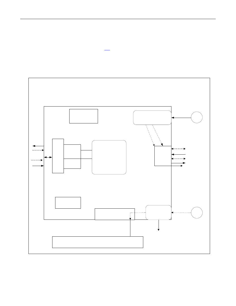
6 BLOCK DIAGRAMS
Figure 6-1. Detailed Block Diagram
MAC
RMII
MII
SDRAM
Interface
Buffer Dev
Div by 2,4,12
Output Clocks
25,50
Mhz
100 Mhz Oscillator
SYSCLKI
SDCLKO
Buffer
Div by 1,2,4,8,10
Output clocks:
50,25 Mhz,2.5 Mhz
50 or 25 Mhz Oscillator
TX_CLK1
RX_CLK1
TCLKI1
RCLKI1
REF_CLKO
50 or 25 Mhz
MDC
REF_CLK
SDRAM
HDLC
+
Serial
Interface
CIR
Line 1
Arbiter
X.86
TSER
RSER
RXD
TXD
Microport
JTAG
IMUX
See also other documents in the category Maxim Integrated Hardware:
- DS80C390 (58 pages)
- DS5001FP (26 pages)
- MAX1416 (14 pages)
- MAX5865 (18 pages)
- MAX1202 (7 pages)
- USBTO232 (31 pages)
- HFAN-09.5.0: Pattern Creator/Converter Software (8 pages)
- MAX-IDE MAXQ Microcontrollers (11 pages)
- MAX6876 Power-Supply Tracker/Sequencer (6 pages)
- MAX6877 Power-Supply Tracker/Sequencer (3 pages)
- 78Q8430 ARM9(920T) Linux Driver Diagnostic Guide (19 pages)
- 78Q8430 Software Driver (54 pages)
- 78Q8430 ST 5100/OS-20 with NexGen TCP/IP Stack (28 pages)
- 6612_OMU_S2_URT_V1_13 (56 pages)
- 6612_OMU_S2+2_URT_V1_14 (58 pages)
- 71M6511 Power Meter IC Family Software (137 pages)
- 71M65xx ADM51 ICE Safety Notice (2 pages)
- 71M6511 2-Layer Demo Board (2 pages)
- 71M6511 4-Layer Demo Board (2 pages)
- 78Q8430 Linux Driver ARM Platform (22 pages)
- 71M6513 Demo Board (2 pages)
- 71M6521DE Energy Meter IC Family Software (138 pages)
- 71M6521 Demo Board (2 pages)
- 71M6531 Demo Board (2 pages)
- 71M6531 Energy Meter IC Family Software (116 pages)
- 71M6533 Demo Board (2 pages)
- 71M6534H Demo Board (2 pages)
- 71M6515H Demo Board (2 pages)
- 73S1209F Evaluation Board (2 pages)
- 73S12xxF (38 pages)
- 73S12xxF Software (93 pages)
- 73S1210F Evaluation Board Lite (2 pages)
- 73S1210F Evaluation Board (2 pages)
- 73S1210F Multi-SAM Evaluation Board Lite (2 pages)
- 73S12xxF USB-CCID Linux DFU Host Application (8 pages)
- 73S1215F Device Firmware Upgrade Host Driver/Application (10 pages)
- 73S12xxF USB-CCID Host GUI (22 pages)
- 73S1215F Windows XP 32 USB CCID and DFU Drivers (15 pages)
- 73S1215F CCID USB Linux Driver (16 pages)
- 73S1215F Evaluation Board (2 pages)
- 73S1215F Evaluation Board Lite (2 pages)
- 73S1217F Evaluation Board (2 pages)
- 73S1217F Evaluation Board Lite (2 pages)
- MAXQ Family (216 pages)