Thernet, Nterface, 13 ethernet interface port – Maxim Integrated DS33Z41 User Manual
Page 42
DS33Z41 Quad IMUX Ethernet Mapper
42 of 167
8.13 Ethernet Interface Port
The Ethernet port interface allows for direct connection to an Ethernet PHY. The interface consists of a
10/100Mbps MII/RMII interface and an Ethernet MAC. In RMII operation, the interface contains 7 signals with a
reference clock of 50MHz. In MII operation, the interface contains 17 signals and a clock reference of 25MHz. The
DS33Z41 can be configured to RMII or MII interface by the Hardware pin RMIIMIIS. If the port is configured for
MII in DCE mode, REF_CLK must be 25MHz. The DS33Z41 will internally generate the TX_CLK and RX_CLK
outputs (at 25MHz for 100Mbps, 2.5MHz for 10Mbps) required for DCE mode from the REF_CLK input. In MII
mode with DTE operation, the TX_CLK and RX_CLK signals are generated by the PHY and are inputs to the
DS33Z41. For more information on clocking the Ethernet Interface, see Section
8.2.2
.
The data received from the MII or RMII interface is processed by the internal IEEE 802.3 compliant Ethernet
MAC. The user can select the maximum frame size (up to 2016 bytes) that is received with the
SU.RMFSRH
and
SU.RMFSRL
registers. The maximum frame length (in bits) is the number specified in
SU.RMFSRH
and
SU.RMFSRL
multiplied by 8. Any programmed value greater than 2016 bytes will result in unpredictable
behavior and should be avoided. The maximum frame size is shown in
Figure 8-7
. The length includes only
destination address, source address, VLAN tag (2 bytes), type length field, data and CRC32. The frame size is
different than the 802.3 “type length field.”
Frames coming from the Ethernet PHY or received from the packet processor are rejected if greater than the
maximum frame size specified. Each Ethernet frame sent or received generates status bits (
SU.TFSH
and
SU.TFSL
and
SU.RFSB0
to
SU.RFSB3
). These are real time status registers and will change as each frame is
sent or received. Hence they are useful to the user only when one frame is sent or received and the status is
associated with the frame sent or received.
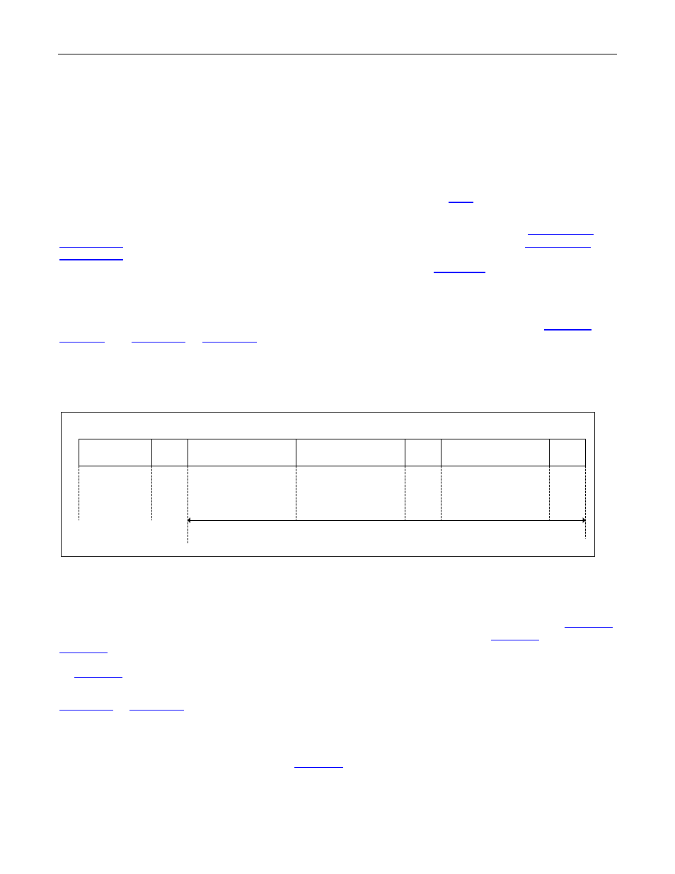
Figure 8-7. IEEE 802.3 Ethernet Frame
Preamble
SFD
Destination Adrs
Source Address
Type
Length
Data
CRC32
7
1
6
6
2
46-1500
4
Max Frame Length
The distant end will normally reject the sent frames if jabber timeout, loss of carrier, excessive deferral, late
collisions, excessive collisions, under run, deferred or collision errors occur. Transmission of a frame under any of
theses errors will generate a status bit in SU.TFSL, SU.TFSH. The DS33Z41 provides user the option to
automatically retransmit the frame if any of the errors have occurred through the bit settings in
SU.TFRC
.
Deferred frames and heartbeat fail have separate resend control bits (
SU.TFRC
.TFBFCB and
SU.TFRC
.TPRHBC). If there is no carrier (indicated by the MAC Transmit Packet Status), the transmit queue
(data from the Serial Interface to the SDRAM to Ethernet Interface) can be selectively flushed. This is controlled
by
SU.TFRC
.NCFQ.
The MAC circuitry generates a frame status for every frame that is received. This real time status can be read by
SU.RFSB0
to
SU.RFSB3
. Note the frame status is the “real time” status and hence the value will change as new
frames are received. Hence the real time status reflects the status in time and may not correspond to the current
received frame being processed. This is also true for the transmitted frames.
Frames with errors are usually rejected by the DS33Z41. The user has the option of accepting frames by settings
in Receive Frame Rejection Control register (
SU.RFRC
). The user can program whether to reject or accept
frames with the following errors: