Pin descriptions, Pin functional description, Unctional – Maxim Integrated DS33Z41 User Manual
Page 14: Escription, 7 pin descriptions
DS33Z41 Quad IMUX Ethernet Mapper
14 of 167
7 PIN DESCRIPTIONS
7.1 Pin Functional Description
Note that all digital pins are inout pins in JTAG mode. This feature increases the effectiveness of board level
ATPG patterns.
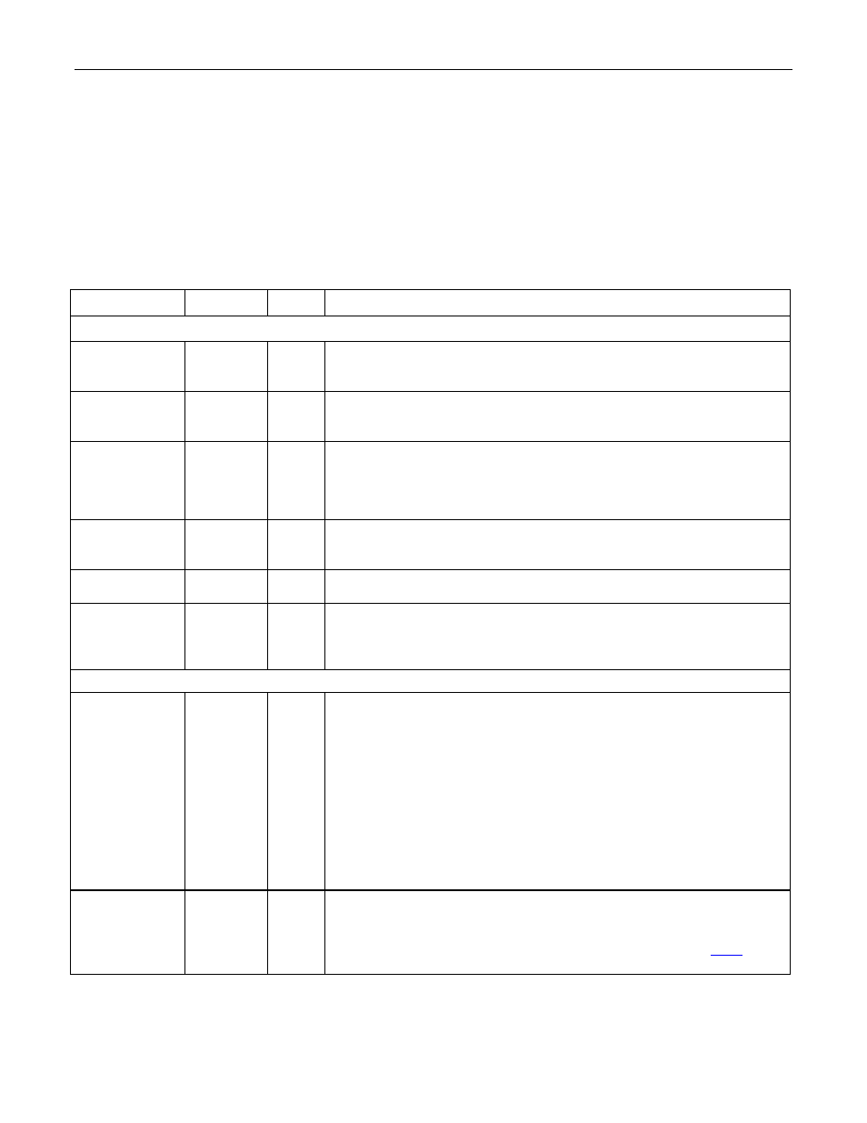
Table 7-1. Detailed Pin Descriptions
Note: I = Input; O = Output; Ipu = Input with pullup; Oz = Output with tri-state; IO = Bidirectional pin; IOz = Bidirectional pin with tri-state.
NAME PIN
TYPE
FUNCTION
SERIAL INTERFACE IO PINS
TCLKI
F1 I
Serial Interface Transmit Clock Input. The clock reference for TSER,
which is output on the rising edge of the clock. TCLKI supports gapped
clocking, up to a maximum frequency of 52MHz.
TSER
F2 O
Transmit Serial Data Output. Output on the rising edge of TCLKI.
Selective clock periods can be skipped for output of TSER with a
gapped clock input on TCLKI. The maximum data rate is 52Mbps.
TSYNC G3 I
Transmit Synchronization Input. An 8lHz synchronization pulse, used
to denote the first Channel 1 of the 8.192Mbps byte-interleaved IBO
data stream. Note that this input is also used to generate the transmit
byte synchronization if X.86 mode is enabled.
RCLKI
G2 I
Serial Interface Receive Clock Input. Reference clock for receive
serial data on RSER. Gapped clocking is supported, up to the
maximum RCLKI frequency of 52MHz.
RSER H1
I
Receive Serial Data Input. Receive Serial data arrives on the rising
edge of the clock.
RSYNC
G1 I
Receive Synchronization Input. An 8kHz synchronization pulse, used
to denote the first Channel 1 of the 8.192Mbps byte-interleaved IBO
data stream. Note that this input is also used to generate the receive
byte synchronization if X.86 mode is enabled.
MII/RMII PORT
REF_CLK
D13 I
Reference Clock (RMII and MII). When in RMII mode, all signals from
the PHY are synchronous to this clock input for both transmit and
receive. This required clock can be up to 50MHz and should have
±100ppm accuracy.
When in MII mode in DCE operation, the DS33Z41 uses this input to
generate the RX_CLK and TX_CLK outputs as required for the
Ethernet PHY interface. When the MII interface is used with DTE
operation, this clock is not required and should be tied low.
In DCE and RMII modes, this input must have a stable clock input
before setting the
RST pin high for normal operation.
REF_CLKO
E13 O
Reference Clock Output (RMII and MII). A derived clock output up to
50MHz, generated by internal division of the SYSCLKI signal.
Frequency accuracy of the REF_CLKO signal will be proportional to the
accuracy of the user-supplied SYSCLKI signal. See Section
8.2.2
for
more information.