RIGOL DG5000 Series User Manual
Page 179

RIGOL
User’s Guide for DG5000
10-29
DG-POD-A Accessories:
Name
Qty.
Description
Data Flat Cable
1
Connect DG5000 and DG-POG-A.
SMB-to-SMA RF Coaxial Lines 9
Connect the digital logic output with the
device under test.
Logic Analyzer Testing Lines
20
Connect the analog output with the
device under test.
Logic Analyzer Testing Clips
20
Used together with the logic analyzer
testing lines.
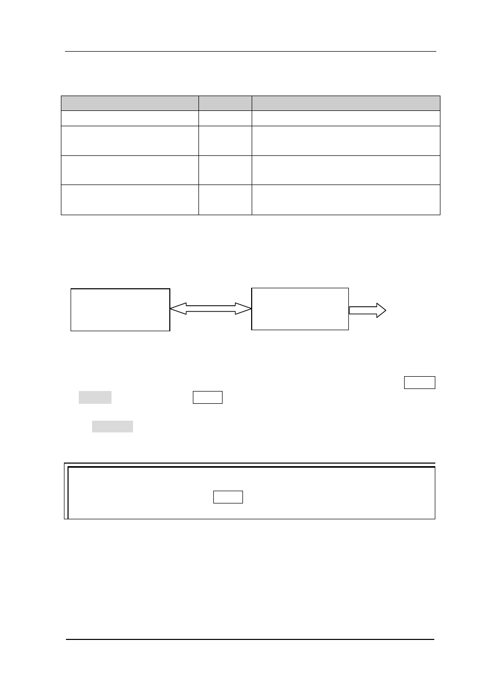
Connect DG5000 with DG-POD-A:
When the connection succeeds, if the system detects a digital module, the shortcut
will be automatically switched to “Digital”. To edit digital waveform data, press Utility
Digital “Power On” User*.
Press Protocol in the digital waveform editing interface to select the desired protocol:
RS232, SPI, IIC or PO.
Tip
During digital waveform editing, User* blinking indicates that users need to press
this key again to apply the modified setting to the output.
The following part introduces how to use the operation menu at the front panel of
DG5000 to configure the digital module to realize digital signal output.
DG-POD-A
DG5000
Digital Output Digital Input Output
Logical Cable
