Channel setting, Sync setting, Channel setting -3 – RIGOL DG5000 Series User Manual
Page 153: Sync setting -3

RIGOL
User’s Guide for DG5000
10-3
Channel Setting
This section takes CH1 for example to illustrate how to set the channel. The setting
method for CH2 is quite the same.
Sync Setting
DG5000 could output the sync signals of basic waveform (except Noise and DC),
Sweep signal, Burst signal and Modulated signal from the Sync connector, which is
located at the rear panel for dual-channel model and at the front panel for
single-channel.
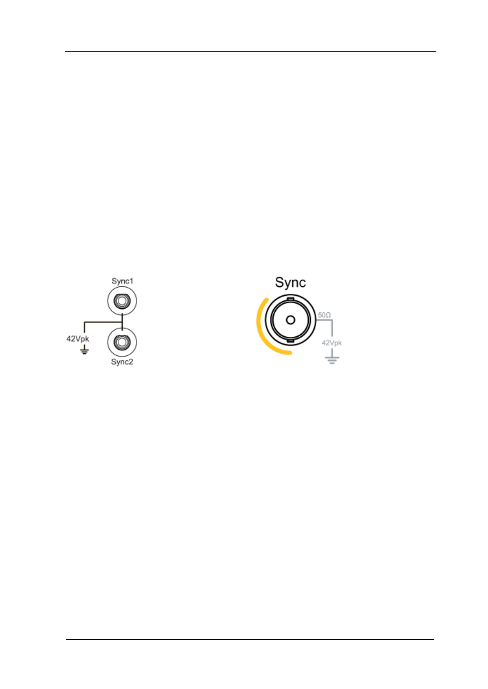
Dual-channel Model Sync Connector Single-channel Model Sync Connector
1.
Sync On/Off
Enable or disable the sync signal on the Sync connector. Press Utility CH1Set
Sync to select “On” or “Off” for the sync signal output.
By default, the sync signal is transmitted to the Sync connector (enabled). If the
sync signal is disabled, the output level on the Sync connector is logic low.
2.
Sync Signals of Various Waveforms
For Sine, Square, Ramp and Pulse, the sync signal is a Square with 50% duty
cycle, which is TTL high level relative to 0 V (or DC offset) when the output is
positive and TTL low level relative to 0 V (or DC offset) when the output is
negative. For Noise, there is no sync signal output.
For an arbitrary waveform, the sync signal is a Square with variable duty
cycle, which is TTL high level when DG5000 outputs the first downloaded
waveform point.
