5 encoder output pulses, 1) signals (2) output phase form – Yaskawa Sigma-5 User Manual: Design and Maintenance - Rotary Motors User Manual
Page 94
4.2 Settings for Common Basic Functions
4-11
Operation
4.2.5 Encoder Output Pulses
Encoder output pulse is the signal which processes the encoder output inside the SERVOPACK and then out-
puts externally in the form of 2-phase pulses (phase A and B) with 90
° phase differential. It is used as the feed-
back of position.
Signals and output phase form are as shown below.
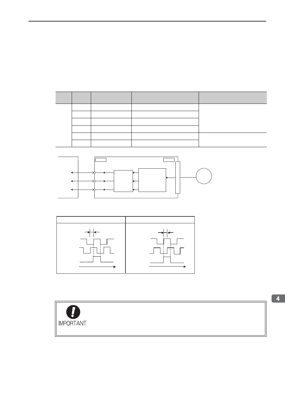
(1) Signals
(2) Output Phase Form
Note: The pulse width of the (Phase C origin pulse) changes according to the setting of the Pn212 and becomes the same
as that for phase A.
Even in reverse rotation mode (Pn000.0 = 1), the output phase form is the same as that for the standard setting
(Pn000.0 = 0).
Type
Signal
Name
Connector
Pin Number
Name
Remarks
Output
PAO
CN1-17
Encoder output pulse: phase A
Output pulses per motor rotation set
in the encoder output pulses (Pn212),
and phase A and phase B are different
from each other in phase by an elec-
tric angle of 90
°.
/PAO
CN1-18
Encoder output pulse: phase /A
PBO
CN1-19
Encoder output pulse: phase B
/PBO
CN1-20
Encoder output pulse: phase /B
PCO
CN1-21
Encoder output pulse: phase C
One pulse is output per motor rota-
tion.
/PCO
CN1-22
Encoder output pulse: phase /C
ENC
CN1 CN2
SERVOPACK
Host controller
Serial
data
PAO
PBO
PCO
Converts
serial data to
pulse.
Dividing
circuit
(Pn212)
If using the SERVOPACK’s phase-C pulse output for a zero point return, rotate the ser-
vomotor twice before starting a zero point return. If the configuration prevents the servo-
motor from returning to the zero point by rotating the servomotor twice, perform a zero
point return at a motor speed of 600 min
-1
or below. If the motor speed is faster than 600
min
-1
, the phase-C pulse output may not be output correctly.
Phase A
Phase B
Phase C
90°
t
Phase A
Phase B
Phase C
t
Forward rotation (phase B leads by 90°) Reverse rotation (phase A leads by 90°
㧕
90°