2 safety function signal (cn8) names and functions, 20 (2) output signals – Yaskawa Sigma-5 User Manual: Design and Maintenance - Rotary Motors User Manual
Page 64
3 Wiring and Connection
3.2.2 Safety Function Signal (CN8) Names and Functions
3-20
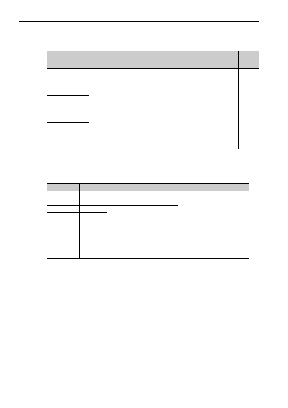
(2) Output Signals
Note: For more information on the allocation of /SO1, /SO2, and /SO3, refer to 3.3.2 Output Signal Allocation.
3.2.2 Safety Function Signal (CN8) Names and Functions
The following table shows the terminal layout of safety function signals (CN8).
∗ Do not use pins 1 and 2. They are connected to the internal circuits.
Signal
Pin No.
Name
Function
Refer-
ence
Section
ALM+
3
Servo alarm output
Turns OFF when an error is detected.
−
ALM-
4
/BK+
(/SO1+)
1
Brake output
Controls the brake. The brake is released when the signal
turns ON.
Allocation can be changed to general-purpose output signals
(/SO1+, /SO1-).
4.2.3
/BK-
(/SO1-)
2
/SO2+
23
General-purpose
output
General-purpose output signals
Note: Set the parameters to allocate functions.
−
/SO2-
24
/SO3+
25
/SO3-
26
FG
Connector
shell
Frame ground
Connected to frame ground if the shield wire of the I/O signal
cable is connected to the connector shell.
−
Signal
Pin No.
Name
Function
/HWBB1-
3
Hard wire base block input 1
Hard wire base block input
Base block (motor current off) when
OFF
/HWBB1+
4
/HWBB2-
5
Hard wire base block input 2
/HWBB2+
6
EDM1-
7
Monitored circuit status output 1
ON when the /HWBB1 and
the /HWBB2 signals are input and the
SERVOPACK enters a base block
state.
EDM1+
8
−
1
*
−
−
−
2
*
−
−