Outline – Yaskawa Sigma-5 User Manual: Design and Maintenance - Rotary Motors User Manual
Page 31
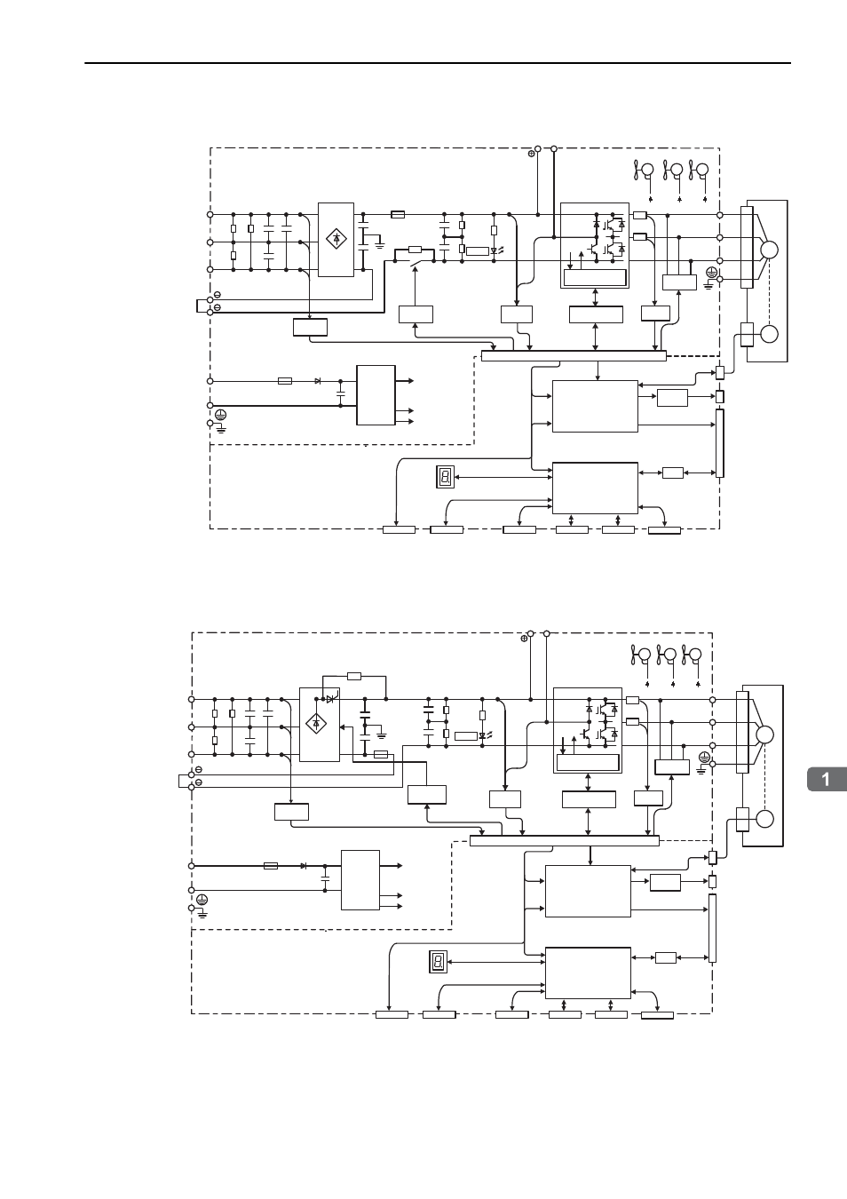
1.5 SERVOPACK Internal Block Diagrams
1-13
Outline
1.5.15 Three-phase 400-V, SGDV-210DE1A, -260DE1A Models
1.5.16 Three-phase 400-V, SGDV-280DE1A, -370DE1A Models
CN2
CN11*
CN12*
CN10*
CN3
CN7
CN8
I/O
CN1
CN5
L1
B1/
B2
L2
L3
1
2
+24V
0V
U
V
W
ENC
M
CHARGE
+15 V
× 4
+5 V
+24 V
+24 V +24 V
+
−
±12 V
Servomotor
Varistor
Voltage
sensor
Control
power
supply
CPU
(Position/speed
calculation, etc.)
Panel display
Digital
operator
Personal
computer
Signal for safety fuction
Analog monitor
output
ASIC
(PWM control, etc.)
Analog
voltage
converter
Current
sensor
Dynamic
brake circuit
+
−
Voltage
sensor
Overheat protector,
overcurrent protector
Gate drive
Relay
drive
Fan 2
Fan 1
Fan 3
+
−
Safety module
Command option
module
Feedback module
Encoder output
pulses
Main circuit
power supply
Control power
supply
(A DC power supply
(24 VDC) is not included.)
* This external input signal is used by the option module.
For details, refer to the manual of the connected option module.
CN2
CN11*
CN12*
CN10*
CN3
CN7
CN8
I/O
CN1
CN5
L1
B1/
B2
L2
L3
1
2
+24V
0V
U
V
W
ENC
M
CHARGE
+15 V
× 4
+5 V
+24 V +24 V +24 V
+
−
±12 V
Servomotor
Varistor
Control
power
supply
CPU
(Position/speed
calculation, etc.)
Panel display
Digital
operator
Personal
computer
Signal for safety fuction
Analog monitor
output
ASIC
(PWM control, etc.)
Analog
voltage
converter
Gate drive
+
−
Fan 2
Fan 1
Voltage
sensor
Thyristor
drive
Current
sensor
Dynamic
brake circuit
Voltage
sensor
Overheat protector,
overcurrent protector
Fan 3
+
−
Safety module
Command option
module
Feedback module
Encoder output
pulses
Main circuit
power supply
Control power
supply
(A DC power supply
(24 VDC) is not included.)
* This external input signal is used by the option module.
For details, refer to the manual of the connected option module.