3 i/o signal allocations, 1 input signal allocations – Yaskawa Sigma-5 User Manual: Design and Maintenance - Rotary Motors User Manual
Page 66
3 Wiring and Connection
3.3.1 Input Signal Allocations
3-22
3.3 I/O Signal Allocations
This section describes the I/O signal allocations.
3.3.1 Input Signal Allocations
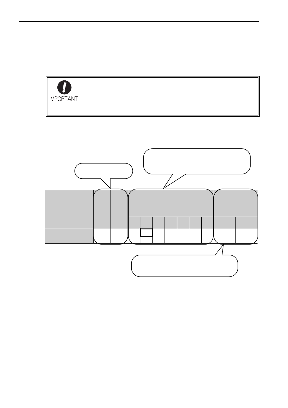
Input signals are allocated as shown in the following table.
Refer to the Interpreting the Input Signal Allocation Tables and change the allocations accordingly.
• Inverting the polarity of the Forward Run Prohibited, and Reverse Run Prohibited sig-
nals will prevent the holding brake from working in case of their signal line disconnec-
tions. If such setting is absolutely necessary, confirm the operation and observe
safety precautions.
• If two or more signals are allocated to the same input circuit, a signal is output with or
logic circuit input signal level is valid for all allocated signals.
Input Signal Names
and Parameters
Validity
Level
Input
Signal
CN1 Pin Numbers
Connection Not
Required
(SERVOPACK
judges the
connection)
13
7
8
9
10
11
12
Always
ON
Always
OFF
Forward Run Prohibited
Pn50A.3
H
P-OT
0
1
2
3
4
5
6
7
8
L
/P-OT
9
A
B
C
D
E
F
Level at which input signal
allocations are valid.
The parameter set values to be used are shown.
Signals are allocated to CN1 pins according to the
selected set values.
Values in cells in bold lines are the factory settings.
If always ON (7) or always OFF (8) is set, signals
will be processed in the SERVOPACK, which will
eliminate the need for wiring changes.