5 three-phase 200-v, sgdv-2r8ae1a model – Yaskawa Sigma-5 User Manual: Design and Maintenance - Rotary Motors User Manual
Page 26
1 Outline
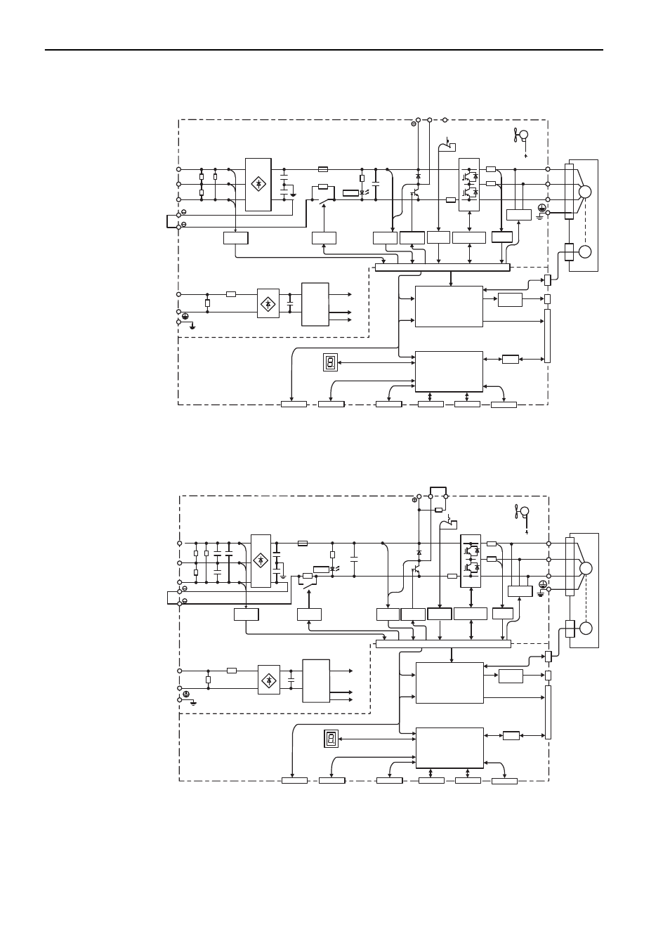
1.5.5 Three-phase 200-V, SGDV-2R8AE1A Model
1-8
1.5.5 Three-phase 200-V, SGDV-2R8AE1A Model
1.5.6 Three-phase 200-V, SGDV-3R8AE1A, -5R5AE1A, -7R6AE1A Models
L1
B1/
B2
B3
L2
L3
1
2
L1C
L2C
U
V
W
+17 V
+5 V
ENC
M
CHARGE
CN2
+
12 V
CN11*
CN12*
CN10*
CN3
CN7
CN8
I/O
CN1
CN5
+
−
±12 V
Servomotor
Fan
Varistor
Voltage
sensor
Varistor
Control
power
supply
CPU
(Position/speed
calculation, etc.)
Panel display
Digital
operator
Personal
computer
Signal for safety fuction
Analog monitor
output
ASIC
(PWM control, etc.)
Analog
voltage
converter
Current
sensor
Dynamic
brake circuit
Gate drive
overcurrent
protector
Temperature
sensor
+
−
Voltage
sensor
Gate
drive
Relay
drive
Main circuit
power supply
Control power
supply
Safety module
Command option
module
Feedback module
Encoder output
pulses
* This external input signal is used by the option module.
For details, refer to the manual of the connected option module.
L1
B1/
B2
B3
L2
L3
1
2
L1C
L2C
U
V
W
+17 V
+5 V
ENC
M
CHARGE
CN2
CN11*
CN12*
CN10*
CN3
CN7
CN8
I/O
CN1
CN5
+
−
±12 V
Servomotor
Fan
Varistor
Voltage
sensor
Varistor
Control
power
supply
CPU
(Position/speed
calculation, etc.)
Panel display
Digital
operator
Personal
computer
Signal for safety fuction
Analog monitor
output
ASIC
(PWM control, etc.)
Analog
voltage
converter
Current
sensor
Dynamic
brake circuit
Gate drive
overcurrent
protector
Temperature
sensor
+
−
Voltage
sensor
Gate
drive
Relay
drive
±12 V
Main circuit
power supply
Control power
supply
Safety module
Command option
module
Feedback module
Encoder output
pulses
* This external input signal is used by the option module.
For details, refer to the manual of the connected option module.