Connection example specifications – Yaskawa Sigma-5 User Manual: Design and Maintenance - Rotary Motors User Manual
Page 130
4.6 Safety Function
4-47
Operation
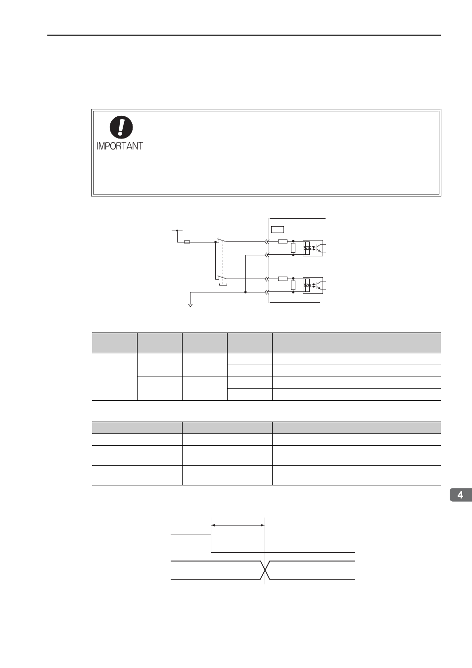
(5) Connection Example and Specifications of Input Signals (HWBB Signals)
The input signals must be redundant. A connection example and specifications of input signals (HWBB sig-
nals) are shown below.
Connection Example
Specifications
The input signals (HWBB signals) have the following electrical characteristics.
If the HWBB function is requested by turning OFF the /HWBB1 and /HWBB2 input signals on the two chan-
nels, power supply to the motor will be turned OFF within 20 ms (see below).
Note: The OFF status is not recognized when the /HWBB1 and /HWBB2 signals are OFF for 0.5 ms or shorter.
For safety function signal connections, the input signal is the 0V common and the output
signal is the source output. This is opposite to other signals described in this manual. To
avoid confusion, the ON and OFF status of signals for safety functions are defined as fol-
lows:
ON: The state in which the relay contacts are closed or the transistor is ON and current
flows into the signal line.
OFF: The state in which the relay contacts are open or the transistor is OFF and no cur-
rent flows into the signal line.
Type
Signal
Name
Pin Number
State
Meaning
Input
/HWBB1
CN8-4
ON
Does not use the HWBB function.
CN8-3
OFF
Uses the HWBB function.
/HWBB2
CN8-6
ON
Does not use the HWBB function.
CN8-5
OFF
Uses the HWBB function.
0 V
CN8
24 V power
supply
Fuse
SERVOPACK
Use a relay or switch
that has micro-current
contacts.
6
5
/HWBB2+
/HWBB2-
4
3
/HWBB1+
/HWBB1-
Switch
Items
Characteristics
Remarks
Internal impedance
3.3 k
Ω
–
Operation movable voltage
range
+11 V to + 25 V
–
Maximum delay time
20 ms
Time from the /HWBB1 and /HWBB2 signals are OFF to
the HWBB function operates.
/HWBB1
/HWBB2
Normal operation
SERVOPACK
State
HWBB state
Within 20 ms
(Normal
operation)
(
Requests motor current shutoff.)
OFF
ON