1) operating procedure – Yaskawa Sigma-5 User Manual: Design and Maintenance - Rotary Motors User Manual
Page 228
6 Utility Functions (Fn
)
6-26
6.16 Vibration Detection Level Initialization (Fn01B)
This function detects vibration when servomotor is connected to a machine and automatically adjusts the
vibration detection level (Pn312) to output more exactly the vibration alarm (A.520) and warning (A.911).
Use this function if the vibration alarm (A.520) or warning (A.911) is not output correctly when a vibration
above the factory setting vibration detection level (Pn312) is detected. In other cases, it is not necessary to use
this function.
The vibration detection function detects vibration elements according to the motor speed.
If the vibration exceeds the detection level calculated by the following formula, the alarm or warning will be
output according to the setting of vibration detection switch (Pn310).
case, a detection sensibility fine adjustment can be set in the detection sensibility Pn311.
(1) Operating Procedure
Follow the steps to adjust the parameter Pn312.
Parameter
Meaning
When Enabled Classification
Pn310
n.
0
Does not detect vibration. (Factory setting)
Immediately
Setup
n.
1
Outputs the warning (A.911) when vibration is
detected.
n.
2
Outputs the alarm (A.520) when vibration is detected.
• The vibration may not be detected because of improper servo gains. Also, not all
kinds of vibrations can be detected. Use the detection result as a guideline.
• Set a proper moment of inertia ratio (Pn103). Improper setting may result in the vibra-
tion alarm, warning misdetection, or non-detection.
• The references that are used to operate your system must be input to execute this
function.
• Execute this function under the operation condition for which the vibration detection
level should be set.
• Execute this function to set the vibration detection level while the motor speed
reaches at least 10% of its maximum.
Detection level =ޓVibration detection level (Pn312[min
-1
])× Detection sensibility (Pn311[%])
100
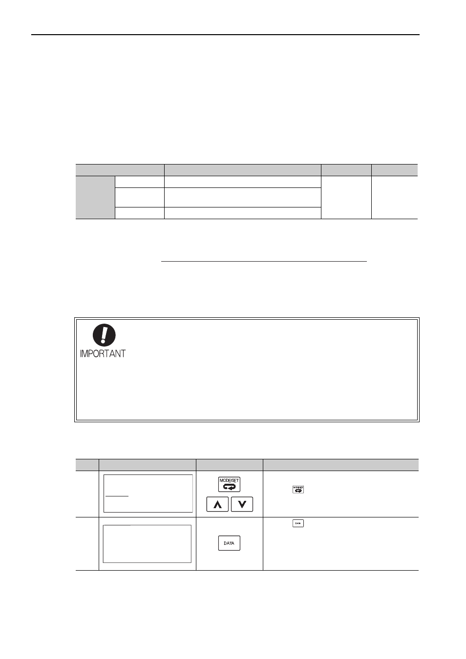
Step
Display Example
Keys
Description
1
Press the
Key to open the Utility Function Mode
main menu and select Fn01B.
2
Press the
Key. The display is switched to the
execution display of Fn01B.
Note: If the display is not switched and “NO-OP” is
displayed in the status display, the Write Prohib-
ited Setting (Fn010 = 0001) is set. Check the
setting and reset. (Refer to 6.12.)
R U N
− F U N C T I O N −
F n 0 1 4 : O p t I n i t
F n 0 1 B : V i b l − v l I n i t
F n 0 1 E : S v M o t O p I D
F n 0 1 F : F B O p M o t I D
L e v e l I n i t
R U N
V i b r a t i o n D e t e c t
S t a r t : [ D A T A ]
R e t u r n : [ S E T ]