3 sglto-35ooooho linear servomotors, 3 sglt, 3 sglt-35h linear servomotors -41 – Yaskawa SGDH Linear Sigma Series User Manual
Page 89: 3 sglt-35h linear servomotors
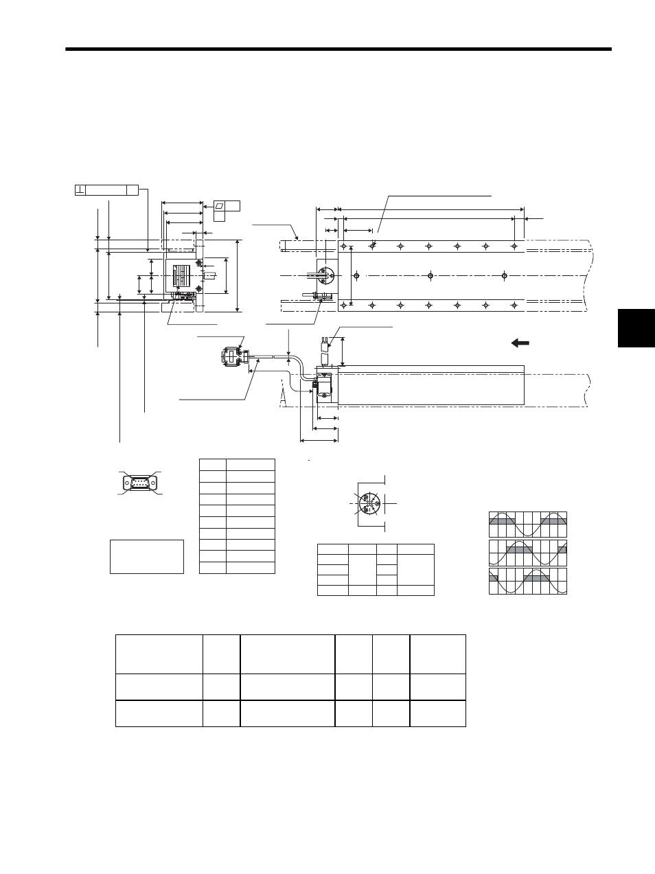
3.8 Dimensional Drawings of SGLTW / SGLTM Linear Servomotors
3-41
3
3.8.3 SGLT-35H Linear Servomotors
(1) Coil Assembly: SGLTW-35H
With a connector made by Tyco Electronics AMP K.K.
The following table and figures show the specifications when a main circuit’s cable connector made by Tyco
Electronics is used for the coil assembly.
* Reference length
TYPE
YASKAWA ELECTRIC
MADE IN JAPAN
W
AV
O/N
S/N
DATE
ins.
Linear SERVO MOTOR
m/s
N
X
P
(L3)
63 min.
Protective tube
Cable
UL20276
AWG28
L1
L2
Wiring specifications
of hall sensor cable
Vu
Vv
Vw
Su
Sv
Sw
0
180
360
540
9
6
1
5
Phase U
Ground
Phase V
Phase W
View from top of coil assembly
Black
Green
-
Phase U
Phase V
Phase W
Ground
Color Code
U
V
W
2mm
2
Wire size
Name
2mm
2
If this cable is bent repetitively, the cable will
disconnect.
Lead specifications of coil assembly
2
×screws
#4
×40 UNC
Nameplate
Magnetic way
Hall sensor
The coil assembly moves in the direction
indicated by the arrow when current flows
in the order of phase U, V, and W.
Pin connector:
17JE-23090-02(D8C)
made by DDK Ltd.
The mating connector
Socket connector type:
17JE-13090-02(D8C)
Stud type: 17L-002C or
ޓޓޓޓޓ17L-002C1
Pin No.
1
2
3
4
5
6
7
8
9
Name
+5VDC
Phase U
Phase V
Phase W
0V
Not used
Not used
Not used
Not used
Hall Sensor Output Signals
Electrical angle(
° )
When the coil assembly moves in the di-
rection indicated by the arrow in the fig-
ure, the relationship between the hall
sensor output signals Su, Sv, Sw and the
inverse power of each motor phase Vu,
Vv, Vw becomes as shown in the figure
below
Inverse
power
(V)
0.15 (0.01) X
15 (0.59)*
20
±
0.1
(0.79
±
0.004
)
70 (2.76)*
66 (2.60)
62.5 (2.46)
12
(0.47)
90 (3.54)*
80
±
0.05
(3.15
±
0.002
)
30
(1.18)
30
(1.18)
28
(1.10)
1
(0.04)
60 (2.36)
120
±
0.1
(4.72
±
0.004
)
15 (0.59)*
(19.2 (0.76): With magnet protection cover)
(19 (0.75): Without magnet protection cover)
(Gap 0.8 (0.03): With magnet
protection cover)
(Gap 1 (0.04): Without magnet
protection cover)
30 (1.18)
φ
4.2
(φ
0.17)
500
±
50
(19.69
±
1.97
)
N
×M6 tapped holes, depth 12 (0.47)
* Reference length
Units: mm (in)
10 (0.39)
20
(0.79)
48
±0.15
(1.89
±0.01
)
100
±
0.15
(3.94
±
0.01
)
500
±50
(19.69
±1.97
)
35 (1.38)
43 (1.69)
Coil Assembly
Model SGLTW-
L1
L2
L3*
N
Approx.
Mass
kg (lb)
35170H
170
(6.69)
144 (5.67)
(48 (1.89)
× 3 (0.12))
16
(0.63)
8
(0.31)
4.7
(10.36)
35320H
315
(12.40)
288 (11.34)
(48 (1.89)
× 6 (0.24))
17
(0.67)
14
(0.55)
8.8
(19.40)