Important – Yaskawa SGDH Linear Sigma Series User Manual
Page 178

7 Wiring
7.1.4 SGLTW and SGLTM Linear Servomotor (T Type with Iron Core)
7-14
* The value in parentheses is the dimension when the magnet protection cover is used.
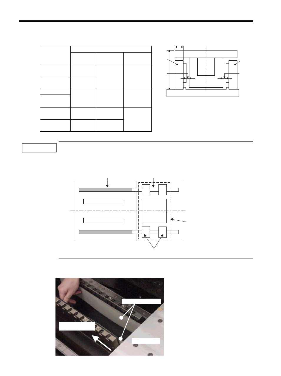
When two or more magnetic way are used, first secure one of the magnetic way only, and then install the
coil assembly in the available space. If using one magnetic way only with insufficient space to extend the
linear guide up to the position of the coil assembly, temporarily mount a dummy linear guide in line with the
magnetic way's.
• Simplified diagram showing installation of dummy linear guide.
2. Insert a thin nonmagnetic (preferably resin) sheet (approximately 0.5-mm thick) in the air gap between the
coil assembly and magnetic way, and move the coil assembly slowly toward the magnetic way.
Coil Assem-
bly Model
SGLTW-
Dimensions in mm (in)
H
A
Air gaps
G1,G2
20AA
55
± 0.3
(2.17
± 0.01)
15
± 0.1
(0.59
± 0.004)
1
± 0.3
(0.04
± 0.01)
(0.8 (0.03))
∗
35A
70
± 0.3
(2.76
± 0.01)
40A
83
± 0.3
(3.27
± 0.01)
19.1
± 0.1
(0.75
± 0.004)
1.4
± 0.3
(0.06
± 0.01)
(1.2 (0.05))
∗
80A
35H
70
± 0.3
(2.76
± 0.01)
15
± 0.1
(0.59
± 0.004)
1
± 0.3
(0.04
± 0.01)
(0.8 (0.03))
∗
50H
85
± 0.3
(3.35
± 0.01)
19.1
± 0.1
(0.75
± 0.004)
A
Magnetic
way
Magnetic
way
Air gap
G1
Air gap
G2
Coil assembly
Linear servomotor side view
(Diagram viewed from the side where the
cable extends from the coil assembly.)
H
IMPORTANT
Magnetic way
Magnetic way
Movable table
Block
Coil
assembly
Standard linear guide
Dummy linear guide
Nonmagnetic sheet
Slowly move coil
assembly.
Movable table
