4 smoothing, 4 smoothing -55, 4) position control block diagram – Yaskawa SGDH Linear Sigma Series User Manual
Page 299: 1) selecting a position reference filter, Important

9.8 Operating Using Position Control
9-55
9
When the external power supply is used, the circuit will be isolated by a photocoupler. When the SERVO-
PACK internal power supply is used, the circuit will not be isolated.
*
: Represents twisted-pair wires.
When the open-collector output is used, input signal noise margin lowers. Set the parameter Pn200.3 to 1.
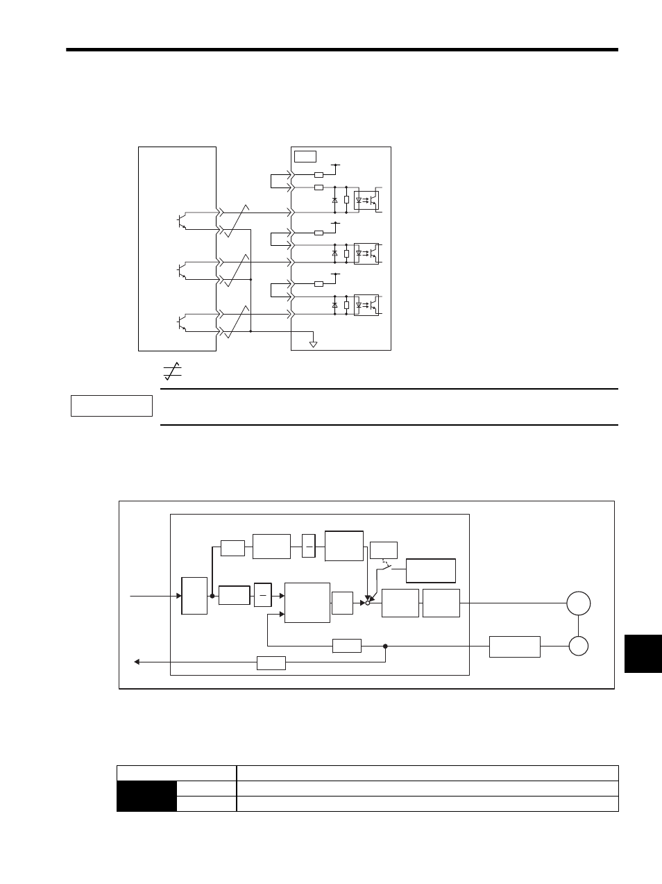
(4) Position Control Block Diagram
A block diagram for position control is shown below.
9.8.4 Smoothing
A filter can be applied in the SERVOPACK to a constant-frequency reference pulse.
(1) Selecting a Position Reference Filter
* After resetting the parameter, turn OFF the power once and turn it ON again.
CN1
7
3
8
1
14
15
12
11
13
18
/PULS
SIGN
/SIGN
CLR
/CLR
PULS
PL1
PL2
PL3
150
Ω
1k
Ω
+12V
∗
Tr1
1.5 V max. at ON
SERVOPACK
Host controller
Photocoupler
IMPORTANT
Kp
M
PG
Pn281
Pn204
Pn202
Pn203
+
-
Pn102
Pn203
Pn202
Pn10A
Pn180
Pn109
Pn200.0
Pn108
B
A
B
A
+
+ +
Differ-
ential
Smoothing
Error
counter
Feed-
forward
gain
Feed-
forward
filter time
constant
Bias
Speed
loop
Current
loop
Dividing
Linear servomotor
Reference
pulse
PG signal
output
SERVOPACK (in position control)
Bias width
addition
× 4
× 256
× 2
× 1
Linear scale
Serial
converter unit
Parameter
Description
Pn207
n.0
Acceleration/deceleration filter
n.1
Average movement filter
