Pulse dividing ratio setting – Yaskawa SGDH Linear Sigma Series User Manual
Page 289

9.7 Operating Using Speed Control with Analog Reference
9-45
9
• Pulse Dividing Ratio Setting
Pn281
Encoder Output Resolution
Setting Range
Setting Unit
Factory Setting
Setting Validation
1 to 255P/{Pn280)
×
4}
1P/{(Pn280)
×
4}
20P/{(Pn280)
×
4}
After restart
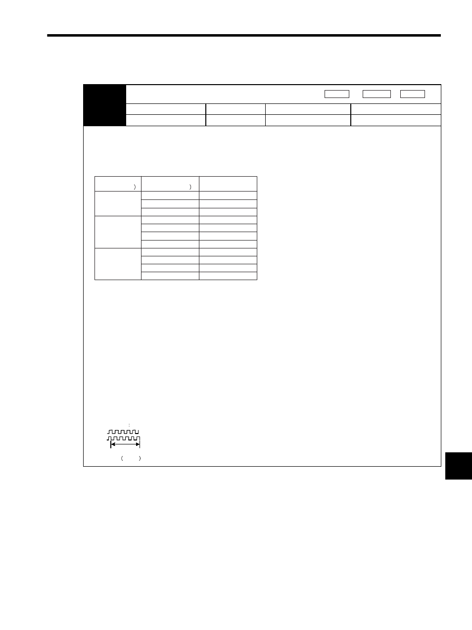
Set the output pulse resolution for PG output signals (PAO, /PAO, PBO, /PBO) externally from the SERVOPACK.
Feedback pulses per linear scale pitch (Pn280) are divided inside the SERVOPACK by the value set in Pn281 before being
output. (Set according to the system specifications of the machine or host controller.)
The setting range varies with the linear servomotor maximum speed (Pn384) and linear scale pitch (Pn280). Refer to the
table below for details.
Note: 1. When the scale pitch is 4
μm, the motor maximum speed is limited to 1 m/s because of the
maximum response frequency of serial converter unit.
2. The SERVOPACK with the software version 32 or higher outputs the alarm “Dividing Pulse
Output Setting Error (A.09)” if the set value does not satisfy the above setting range or the set-
ting conditions.
The SERVOPACK with the software version before 32 cannot output correctly the divided
pulses if the set value does not satisfy the above setting range or the setting condition.
3. The upper limit of encoder output resolution is limited by the frequency dividing specification
of serial converter unit.
Setting Example
When the linear scale pitch = 20
μm (Pn280=20) and the motor maximum speed = 5 m/s (Pn384=50),
Pn281 = 31 is accepted, but Pn281 = 32 is not accepted and A.09 is output.
Output Example
When Pn281 = 20 (20-edge output (5-pulse output) per linear scale pitch),
Speed
Position
Force
Motor Max. Speed
(Pn384) (0.1m/s
Scale Pitch
(Pn280) (
μm
Encoder Output
Resolution (Pn281)
1 to 63
50
40
20
4
40
20
50
40
20
10
10
8
4
2
1 to 127
1 to 255
1 to 255
1 to 255
1 to 31
1 to 31
1 to 63
1 to 63
1 to 127
1 to 127
Preset value 20
Linear scale
pitch Pn280
PAO
PBO
