2 sglfo-35 linear servomotors, 2 sglf, 2 sglf-35 linear servomotors -29 – Yaskawa SGDH Linear Sigma Series User Manual
Page 77: 2 sglf-35 linear servomotors
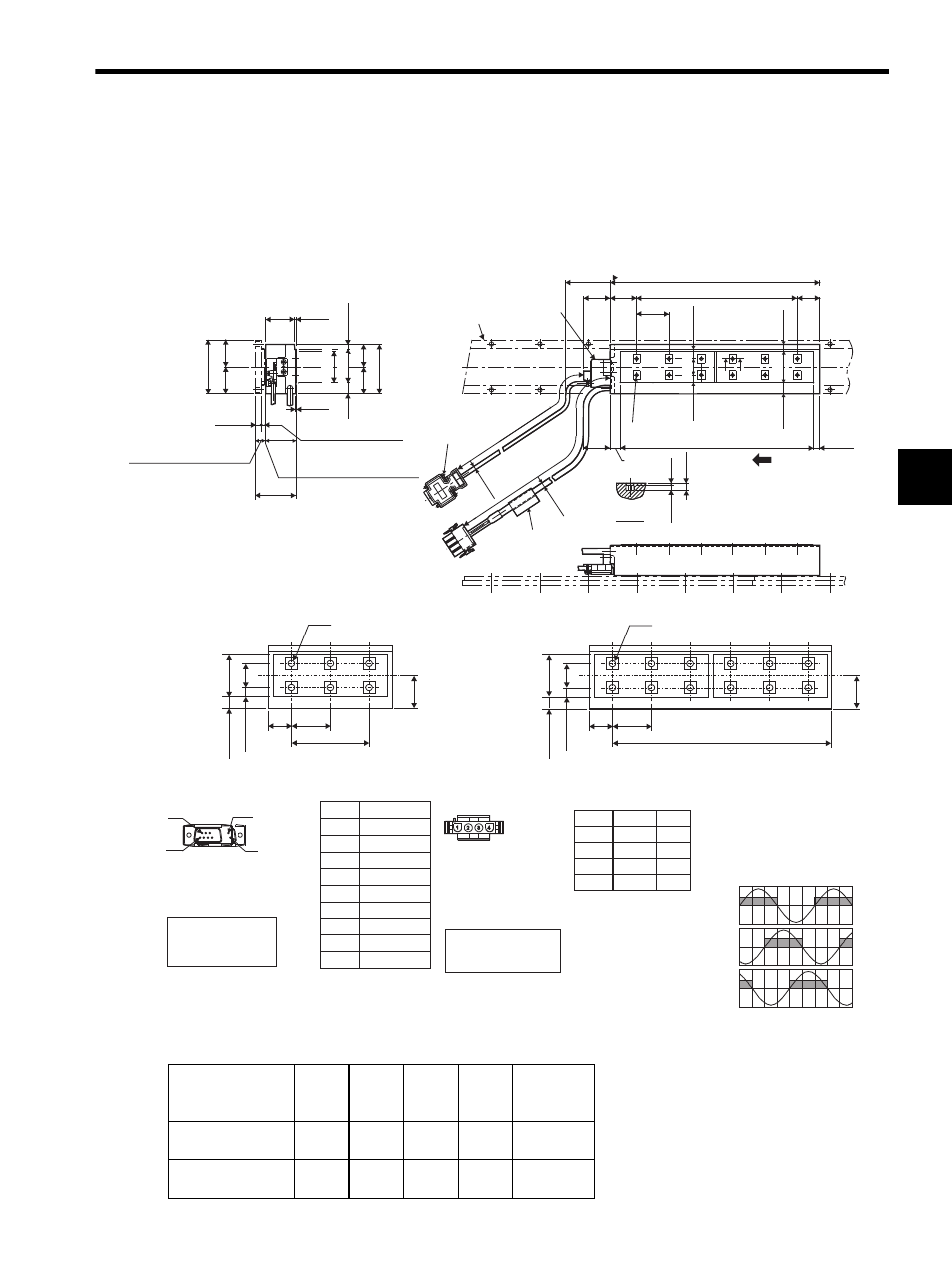
3.7 Dimensional Drawings of SGLFW/SGLFM Linear Servomotors
3-29
3
3.7.2 SGLF-35 Linear Servomotors
(1) Coil Assembly: SGLFW-35A
With a connector made by Tyco Electronics AMP K.K.
The following table and figures show the specifications when a main circuit’s cable connector made by Tyco
Electronics is used for the coil assembly.
A
㧙A
A
A
L1
φ
6.1
(φ
0.24)*
35 (1.38)
L3
30 min.
L2
Nameplate
50 min.
Hall sensor
Magnetic way
2
×screws
#4-40 UNC
The coil assembly moves in the
direction indicated by the arrow
when current flows in the order
of phase U, V, and W.
See the figures
and
below.
Plug type: 350779-1
Pin type: 350218-3 or
ޓޓޓ350547-3 (No.1 to 3)
ޓޓޓ350654-1
ޓޓޓ350669-1 (No.4)
The mating connector
Cap type: 350780-1
Socket type: 350536-3 or
ޓޓޓޓޓ350550-3
Hall Sensor
Connector Specifications
Pin connector type:
7JE-23090-02(D8C)
made by DDK Ltd.
The mating connector
Socket connector type:
17JE-13090-02(D8C)
Stud type: 17L-002C or
ޓޓޓޓޓ17L-002C1
Pin No.
1
2
3
4
5
6
7
8
9
Name
+5V (Power supply)
Phase U
Phase V
Phase W
0V (Power supply)
Not used
Not used
Not used
Not used
Linear Servomotor
Connector Specifications
Hall Sensor Output Signals
Electrical angle(
° )
Vu
Vv
Vw
Su
Sv
Sw
0
180
360
540
When the coil assembly moves in the di-
rection indicated by the arrow in the fig-
ure, the relationship between the hall
sensor output signals Su, Sv, Sw and the
inverse power of each motor phase Vu,
Vv, Vw becomes as shown in the figure
below.
Pin No.
1
2
3
4
Name
Phase U
Phase V
Phase W
FG
Red
White
Black
Green
30
(1.18)
SGLFW-35 120A
ޓ SGLFW-35 230A
9
6
1
5
made by Tycon Electronics AMP K.K.
Lead
Color
Inverse
power
(V)
32
(1.26)*
2 (0.08)
5.5 (0.22)
55 (2.17)
25
(0.98)
30
(1.18)
0.5
(0.02)
60 (2.36)*
30
(1.18)*
30
(1.18)*
6 (0.24)*
34
(1.34)
12.5
(0.49)
45
±
0.1
(1.77
±
0.004
)
(Gap1 (0.04): Without magnet
protection cover)
(Gap 0.8 (0.03): With magnet
protection cover)
(4 (0.16): Without magnet
protection cover)
(4.2 (0.17): With magnet
protection cover)
(10.2 (0.40): With magnet
protection cover)
(10 (0.39): Without magnet
protection cover)
6
×M4 tapped holes, depth 5.5 (0.22)
72 (2.83)
36 (1.42)
30
(1.18)
12.5 (0.49)
8.5 (0.33)
35 (1.38)
18 (0.71)
30
(1.18)
30
(1.18)
36
(1.42)
10.5
(0.41)*
8.5
(0.33)*
500
±50
(19.69
±1.97
)
500
±50
(19.6
9
±1.
97
)
φ
4
.2
(φ
0.17)*
5.5
(0.22)
2.5
(0.98)
8
(0.31)
12
(0.47)
12
×M4 tapped holes, depth 5.5 (0.22)
12.5
(0.49)*
7.5
(0.30)*
7 (0.28)
180 (7.09)
(36 (1.42)
× 5 (0.20))
30
(1.18)
35 (1.38)
18 (0.71)
12.5 (0.49)
8.5 (0.33)
30
(1.18)
36 (1.42)
* Reference length
Units: mm (in)
25 (0.98)
35 (1.38)*
37 (1.46)
18 (0.71)
Coil Assembly
Model SGLFW-
L1
L2
L3
N
Approx.
Mass
kg (lb)
35120A
127
(5.0)
72
(2.83)
108
(4.25)
6
(0.24)
1.3
(2.87)
35230A
235
(9.25)
180
(7.09)
216
(8.50)
12
(0.47)
2.3
(5.07)