9) setting the mass ratio, 10) setting the overtravel signal, 11) setting force limit – Yaskawa SGDH Linear Sigma Series User Manual
Page 261: 12) checking or adjusting polarity detection

9.2 Trial Operation Using SERVOPACK Internal References
9-17
9
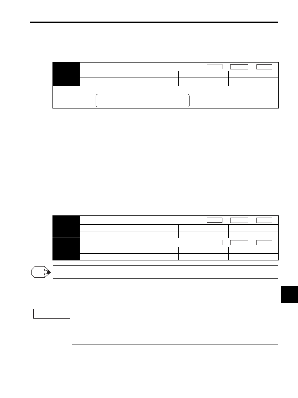
(9) Setting the mass ratio
Set the mass ratio (Pn103) before starting the polarity detection.
* This setting range is applicable for software version 32 or later. The range for software earlier than ver-
sion 32 is 0% to 10,000%.
(10) Setting the Overtravel Signal
Polarity detection cannot start in overtravel state.
When using the overtravel function, connect the signal wires and use in base block status.
When not using the overtravel function, set the parameters Pn50A.3 to 8 and Pn50B.0 to 8 (OT signal disabled).
The setting validation is required to enable the settings. For details, refer to 9.6.3 Setting the Overtravel Limit
Function.
(11) Setting Force Limit
To prevent danger during setup of the linear servomotor, the factory settings for the forward force limit (Pn483)
and reverse force limit (Pn484) parameters are set to small value (factory setting: 30%).
If the force limit is set after (5) Setting the Linear Scale Pitch and (7) Checking the Feedback Signal, overrun will
not occur. Increase the value in the parameters up to the required force. Set the value to the maximum value if no
particular restricting conditions apply.
If the force limit is set too high, polarity detection may not operate normally.
(12) Checking or Adjusting Polarity Detection
Check whether the polarity detection is operating normally.
1. The linear servomotor is turned ON during polarity detection, so take measures to avoid electric shock.
The linear servomotor will make large movements during detection, so do not stand near the coil assem-
bly.
2. Polarity detection depends on many factors, such as mass ratio, friction, and cable tension. If any error
occurs because of one of these factors, the setting may be incorrect.
Pn103
Mass Ratio
Setting Range
Setting Unit
Factory Setting
Setting Validation
0 to 20000 %
∗
1 %
0 %
Immediately
Use the following formula to obtain the mass ratio.
Speed
Position
Force
Mass ratio (Pn103) =
Coil assembly mass
Load mass (including mass of coil assembly) −1 × 100 [%]
Pn483
Forward Force Limit
Setting Range
Setting Unit
Factory Setting
Setting Validation
0 to 800 %
1 %
30 %
Immediately
Pn484
Reverse Force Limit
Setting Range
Setting Unit
Factory Setting
Setting Validation
0 to 800 %
1 %
30 %
Immediately
Speed
Position
Force
Speed
Position
Force
INFO
IMPORTANT
