HEIDENHAIN IK 5394-3D User Manual
Page 388
5-28
Chapter 5
Tolerancing & Templates
Parallelism/Co-planarity tolerance (linear features)
Use parallelism as an orientation tolerance for cylinders, cones, and lines. Par-
allelism tolerancing compares the axial orientation of the selected feature to the
axis of a reference feature. The actual tolerance zone is a cylindrical area around
the axis of the tolerance feature. Specify the diameter of the cylindrical toler-
ance zone to create the tolerance. Tolerancing compares the orientation of the
axis of the toleranced feature to a reference feature.
Use co-planarity as an orientation tolerance between planes. Two planes spaced
evenly apart with the same orientation are said to be co-planar.
To perform a parallelism tolerance
Step 1
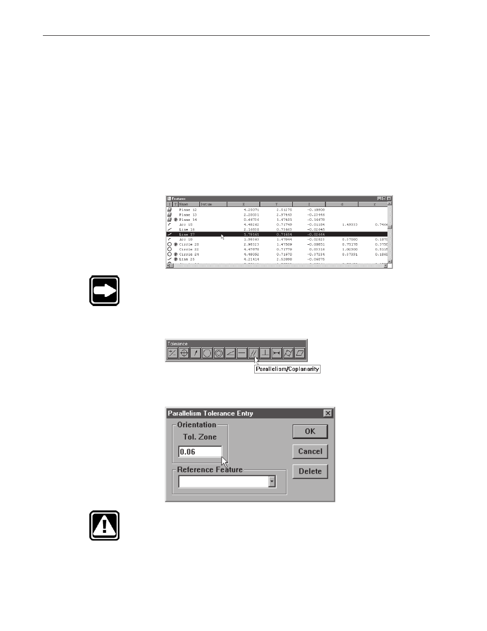
Highlight the desired feature in the features list.
NOTE
Use a linear features only. Parallelism tolerances do not apply
to other types of features.
Step 2
Click the parallelism/co-planarity button on the tolerance toolbar.
Step 3
Enter a value in the tolerance zone box as shown.
CAUTION
Enter tolerance values in the appropriate units of measurement.
For example, if you are measuring in metric (mm) enter tolerance
data in metric (mm).