4 miscellaneous functions f or r otary ax es – HEIDENHAIN iTNC 530 (34049x-08) ISO programming User Manual
Page 435
HEIDENHAIN iTNC 530
435
12.4 Miscellaneous functions f
or r
otary ax
es
Automatic compensation of machine geometry
when working with tilted axes: M114 (software
option 2)
Standard behavior
The TNC moves the tool to the positions given in the part program. If
the position of a tilted axis changes in the program, the resulting offset
in the linear axes must be calculated by a postprocessor and traversed
in a positioning block. As the machine geometry is also relevant, the
NC program must be calculated separately for each machine tool.
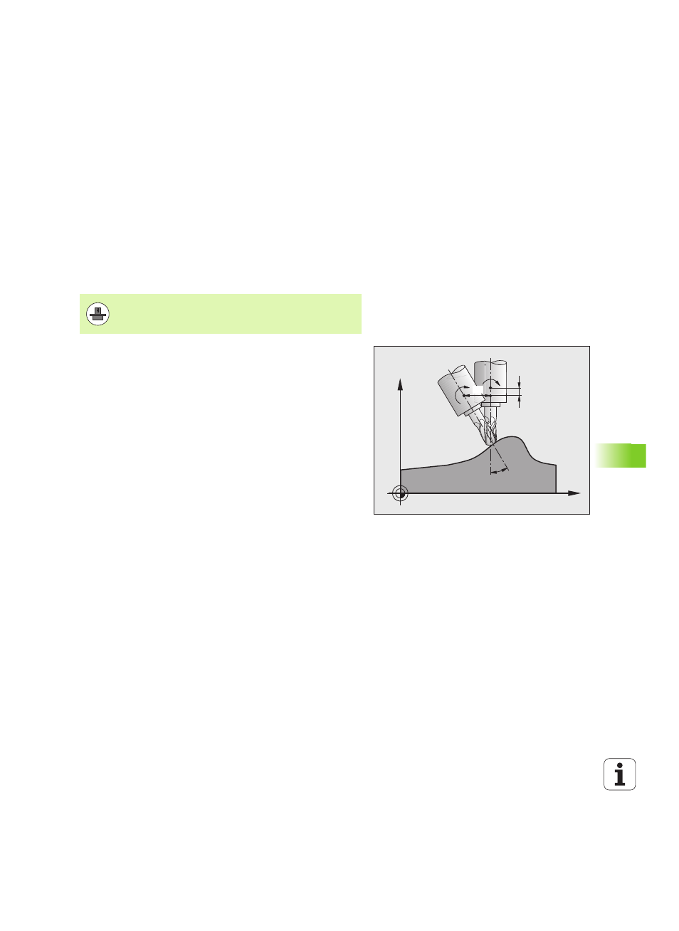
Behavior with M114
If the position of a controlled tilted axis changes in the program, the
TNC automatically compensates the tool offset by a 3-D length
compensation. As the geometry of the individual machine tools is set
in machine parameters, the TNC also compensates machine-specific
offsets automatically. Programs only need to be calculated by the
postprocessor once, even if they are being run on different machines
with TNC control.
If your machine tool does not have controlled tilted axes (head tilted
manually or positioned by the PLC), you can enter the current valid
swivel head position after M114 (e.g. M114 B+45, Q parameters
permitted).
The radius compensation must be calculated by a CAD system or by a
postprocessor. A programmed radius compensation RL/RR will result
in an error message.
If the tool length compensation is calculated by the TNC, the
programmed feed rate refers to the point of the tool. Otherwise it
refers to the tool datum.
The machine geometry must be specified by the machine
tool builder in the description of kinematics.
X
Y
dB
dz
dx
B
B