Network requirements, Configuration procedure – H3C Technologies H3C SecBlade NetStream Cards User Manual
Page 142
127
[SecBlade] interface gigabitethernet 0/2
[SecBlade-GigabitEthernet0/2] ip address 192.168.10.100 255.255.0.0
The ping operation from Host A to Host B is unsuccessful because they are isolated at Layer 2 and Layer
3.
# Configure local proxy ARP to allow communication between Host A and Host B at Layer 3.
[SecBlade-GigabitEthernet0/2] local-proxy-arp enable
The ping operation from Host A to Host B is successful after the configuration.
Local proxy ARP configuration example in isolate-user-VLAN
Network requirements
As shown in
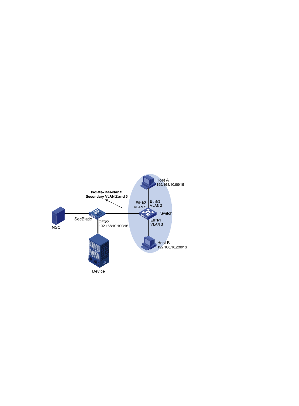
, Switch is attached to the SecBlade. VLAN 5 on Switch is an isolate-user-VLAN,
which includes uplink port Ethernet 1/2 and two secondary VLANs, VLAN 2 and VLAN 3. Ethernet 1/3
belongs to VLAN 2, and Ethernet 1/1 belongs to VLAN 3. Host A belongs to VLAN 2 and connects to
Ethernet 1/3 of Switch. Host B belongs to VLAN 3 and connects to Ethernet 1/1 of Switch.
As Host A and Host B belong to different secondary VLANs, they are isolated at Layer 2. Configure local
proxy ARP on the SecBlade to implement Layer 3 communication between Host A and Host B.
Figure 44 Network diagram for local proxy ARP configuration in isolate-user-VLAN
Configuration procedure
1.
Configure Switch.
# Create VLAN 2, VLAN 3, and VLAN 5 on Switch. Add Ethernet 1/3 to VLAN 2, Ethernet 1/1 to VLAN
3, and Ethernet 1/2 to VLAN 5. Configure VLAN 5 as the isolate-user-VLAN, and VLAN 2 and VLAN 3
as secondary VLANs. Configure the mappings between isolate-user-VLAN and the secondary VLANs.
[Switch] vlan 2
[Switch-vlan2] port ethernet 1/3
[Switch-vlan2] quit
[Switch] vlan 3
[Switch-vlan3] port ethernet 1/1
[Switch-vlan3] quit