Configuration procedure – H3C Technologies H3C SecBlade NetStream Cards User Manual
Page 141
126
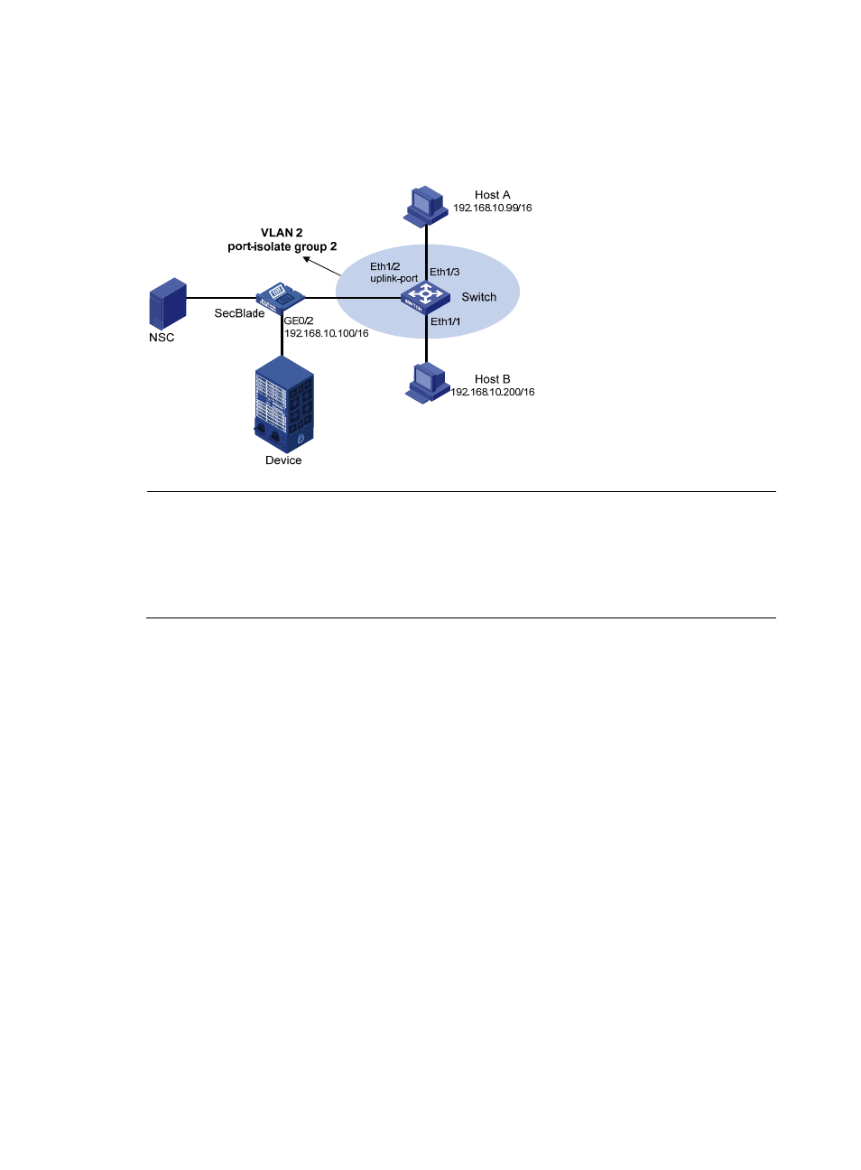
Configure port isolation on Ethernet 1/3 and Ethernet 1/1 of Switch to isolate Host A from Host B at
Layer 2. Enable local proxy ARP on the SecBlade to allow communication between Host A and Host B
at Layer 3.
Figure 43 Network diagram for local proxy ARP between isolated ports
NOTE:
In this configuration example, suppose all traffic between the hosts is blocked, so you need to configure
local proxy ARP on GigabitEthernet 0/2 of the SecBlade to enable communication between Host A and
Host B. If the two ports (Ethernet 1/3 and Ethernet 1/1) on Switch are isolated only at Layer 2, you can
enable communication between the two hosts by configuring local proxy ARP on VLAN-interface 2 of
Switch.
Configuration procedure
1.
Configure Switch.
# Add Ethernet 1/3, Ethernet 1/1 and Ethernet 1/2 to VLAN 2. Configure port isolation on Host A and
Host B.
[Switch] port-isolate group 2
[Switch] vlan 2
[Switch-vlan2] port ethernet 1/3
[Switch-vlan2] port ethernet 1/1
[Switch-vlan2] port ethernet 1/2
[Switch-vlan2] quit
[Switch] interface ethernet 1/3
[Switch-Ethernet1/3] port-isolate enable group 2
[Switch-Ethernet1/3] interface ethernet 1/1
[Switch-Ethernet1/1] port-isolate enable group 2
[Switch-Ethernet1/1] interface ethernet 1/2
[Switch-Ethernet1/2] port-isolate uplink-port group 2
2.
Configure the SecBlade.
# Specify the IP address of GigabitEthernet 0/2.