Configuration procedure – H3C Technologies H3C MSR 5600 User Manual
Page 112

99
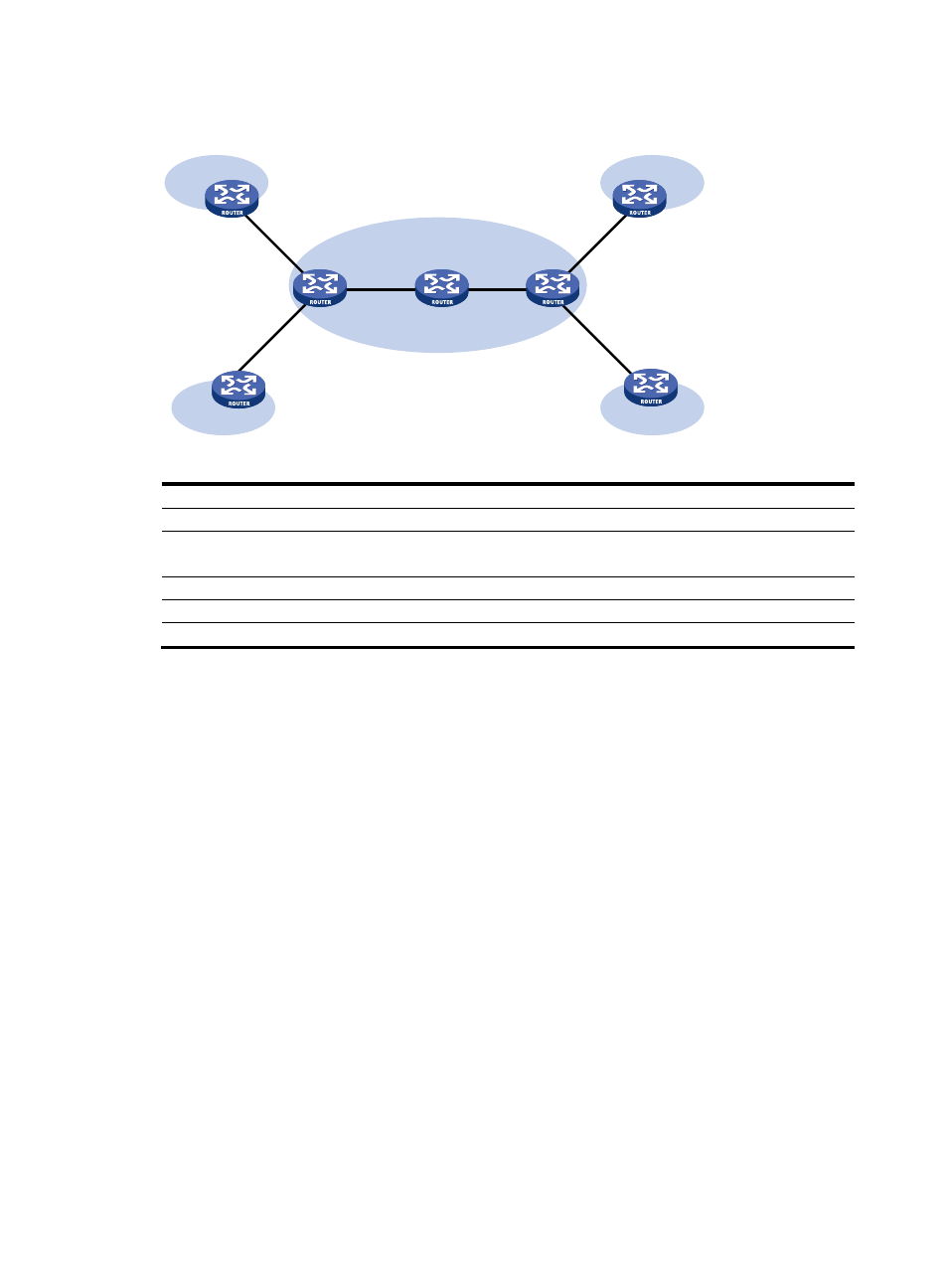
Figure 38 Network diagram
Device Interface
IP
address
Device
Interface IP
address
CE 1
S2/0
10.1.1.1/24
PE 1
S2/0
10.1.1.2/24
CE 2
CE 3
S2/0
S2/0
10.2.1.1/24
10.3.1.1/24
S2/1
S2/2
172.1.1.1/24
10.2.1.2/24
CE 4
S2/0
10.4.1.1/24
PE 2
S2/0
10.3.1.2/24
P S2/0
172.1.1.2/24
S2/1
172.2.1.2/24
S2/1 172.2.1.1/24
S2/2 10.4.1.2/24
Configuration procedure
Prior to performing the following configuration, be sure you have completed MPLS VPN-related
configurations, and make sure of the reachability between CE 1 and PE 1, between PE 1 and PE 2, and
between PE 2 and CE 3. For information about configuring MPLS VPN, see MPLS Configuration Guide.
1.
Set the IP address for each interface as shown in
. (Details not shown.)
2.
Configure CE 1:
# Enable the NTP service.
[CE1] ntp-service enable
# Specify the local clock as the reference source, with the stratum level 2.
[CE1] ntp-service refclock-master 2
3.
Configure PE 2:
# Enable the NTP service.
[PE2] ntp-service enable
# Specify CE 1 in VPN 1 as the NTP server of PE 2.
[PE2] ntp-service unicast-server 10.1.1.1 vpn-instance vpn1
4.
Verify the configuration:
# Display the IPv4 NTP association information and status on PE 2 a certain period of time later.
The information should show that PE 2 has been synchronized to CE 1, with the stratum level 3.
[PE2] display ntp-service status
CE 1
CE 2
CE 4
CE 3
PE 1
PE 2
P
VPN 1
VPN 2
VPN 1
VPN 2
S2/0
S2/0
S2/2
S2/0
S2/1
S2/1
S2/0
S2/0
S2/0
S2/0
S2/2
S2/1
MPLS backbone
