Parallel interface signals behaviour – Compuprint 4247-Z03 Programmer Manual User Manual
Page 351

The pins 1 to 14 of the printer are connected to the pins with the same number of the parallel port of the
host.
The pins 19 to 30 of the printer are connected to the pins 18 to 25 of the parallel port of the host.
The pins 31, 32 and 36 of the printer are connected respectively to the pins 16, 15 and 17 of the parallel port
of the host.
1284 Mode signal names are shown with their Compatibility mode (Centronics) names in parenthesis ( ) for
the bidirectional link.
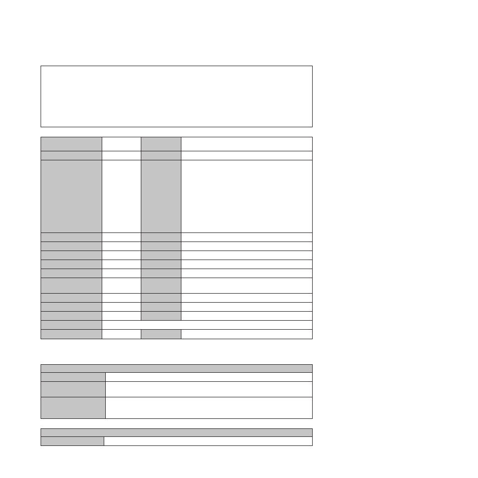
Signal Name
Pin N° for
Signal Wire
Pin N° for
Return Wire
Source
HostClk (nStrobe)
1
19
HOST
AD1 (Data 1)
2
20
HOST in Compatibility mode and negotiation phase.
AD2 (Data 2)
3
21
AD3 (Data 3)
4
22
NOT USED in Nibble mode.
AD4 (Data 4)
5
23
AD5 (Data 5)
6
24
BIDIRECTIONAL in Byte mode.
AD6 (Data 6)
7
25
AD7 (Data 7)
8
26
AD8 (Data 8)
9
27
PrtClk (nAck)
10
28
PRINTER
PrtBusy (Busy)
11
29
PRINTER
AckDataReq (PError)
13
28
PRINTER
Xflag (Select)
14
28
PRINTER
HostBusy (nAutofd)
15
30
HOST
Peripheral Logic High
(+5 V)
18
PRINTER
n.a. (nInit)
31
30
HOST
nDataAvail (NFault)
32
29
PRINTER
1284 Active (NSelectIn)
36
30
Common Logic Ground
16 and Return Wires
Chassis Ground
17
Parallel Interface Signals Behaviour
HostClk /nWrite (nStrobe)
Compatibility Mode:
Set Active low to transfer data into printer input latch. Data is valid while nStrobe is low.
Negotiation Phase:
Set active low to transfer extendibility request value into printer input latch. Data is valid
on the falling edge of HostClk.
Reverse Data Transfer
Phase:
Set high during Nibble Mode transfer to avoid latching data into printer. Pulsed low
during Byte Mode transfers to acknowledge transfer of data from the printer. The printer
shall ensure that this pulse does not transfer a new data into the printer input latch.
AD1 ... AD8 (Data 1 ... Data 8)
Compatibility Mode:
Forward channel data.
Appendix E. Interfaces
331
