Line, Marker, Character string – Compuprint 4247-Z03 Programmer Manual User Manual
Page 194

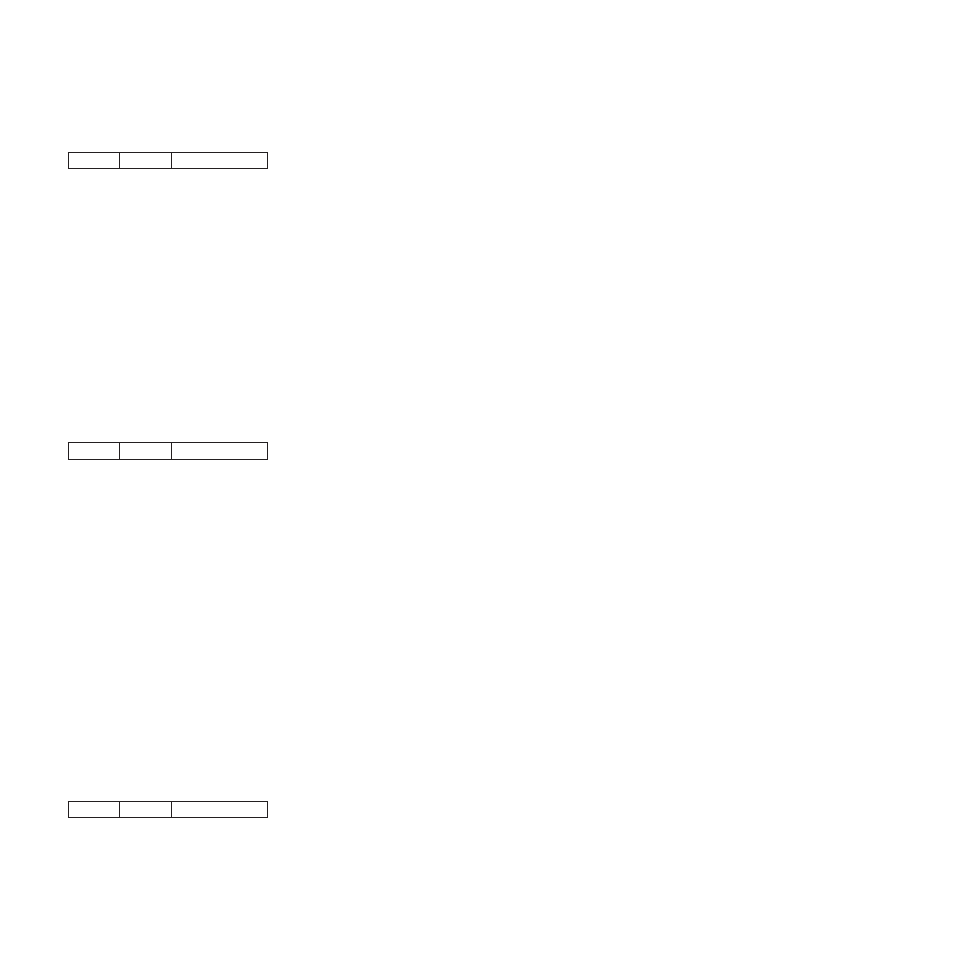
Line
C1
L1
P1-Pn
Description: This order specifies one or more connected lines.
L1 is a one-byte value that specifies the length of the parameter field that follows. The value of L1 must be
a multiple of four and cannot be zero. If L1 equals four, no line is drawn, but the printer updates the
graphics current position to the points specified by parameters P1 to P4.
Parameters P1 and P2 form a two byte value that specifies the first X coordinate point. Parameters P3
and P4 form a two byte value that specifies the first Y coordinate point. Parameters P5 to P8, if present,
specify the second X and Y coordinate points. The printer draws a line from the point specified by the first
pair of coordinates to the point specified by the second pair of coordinates. If additional coordinate pairs
are present, the printer draws additional lines from the previous end point to the next coordinate pair.
This order uses the current values of color, mix, line type, and line width.
Following this order, the printer updates the graphics current position to the last end point specified in the
order.
Marker
C2
L1
P1-Pn
Description: This order specifies one or more marker symbols to place at the points specified by pairs of
coordinates. The specified location is the center of the marker.
A previously specified Set Marker Symbol order determines the marker symbol the printer uses. If no
previous Set Marker Symbol order was processed, the printer uses the current graphics default marker
symbol. The printer uses the current values of color, mix, background mix, marker precision, marker set,
and marker symbol when drawing the markers.
L1 is a one-byte value that specifies the length of the parameter field that follows. The value of L1 must be
a multiple of four. If L1 equals zero, the printer does not draw a marker.
Parameters P1 and P2 form a two byte value that specifies the X coordinate point for the first marker.
Parameters P3 and P4 form a two byte value that specifies the Y coordinate point for the first marker.
Parameters P5 to Pn, if present, specify the X and Y coordinate points for additional markers.
This order updates the current graphics position to the coordinates of the last end point.
Note: The marker cell size is constant 3 mm (0.12 in. [17/144 in.]). The scaling factor used in defining a
graphics area does not affect the size of the marker. If markers are used near the edge of a defined
graphics area, scaling the graphics may result in the markers being clipped from the printable
graphics area.
Character String
C3
L1
P1-Pn
Description: This order draws a character string starting at the specified location. A previous Set
Character Set order specifies the font to use for drawing the character string. If no previous Set Character
Set order was processed, the printer uses the drawing default character set.
174
Programmer Manual
