Write graphics control (wgc), Graphic area position control (gap) – Compuprint 4247-Z03 Programmer Manual User Manual
Page 168

Write Graphics Control (WGC)
Length
D684
Flag
Correlation ID (Optional)
DATA
GAP
GOC
GDD
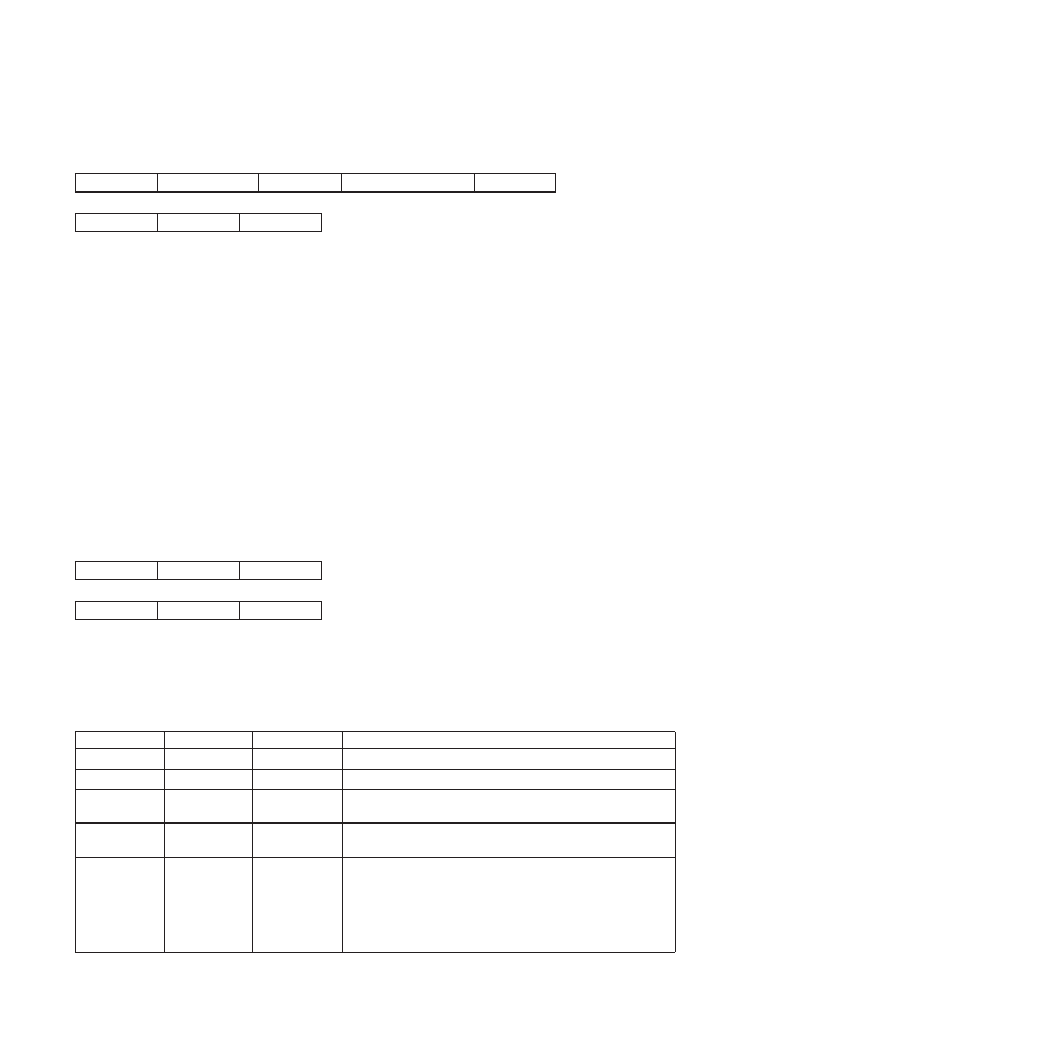
The Write Graphics Control command causes the printer to enter the graphics block state. The parameters
of this command define the size, placement, and orientation of the graphic block area and establish the
initial conditions for interpreting the graphic data. Receiving the End command in the graphic block state
terminates the processing of the graphic data.
The Write Graphics Control data consists of three consecutive structured fields:
v
The Graphic Area Position control defines the position of the graphics picture on the page.
v
The Graphic Output Control (GOC) defines the size of this picture on the page.
v
The Graphic Data Descriptor (GDD) defines the size of the graphics window and the default
characteristics of the graphics picture.
Each structured field contains a two byte length field, then a two byte structured field ID, and finally a data
field.
Note: The quality of the graphics output is affected by the graphics mode and direction parameter values
selected at the operator panel (see the User’s Guide for your model printer), and by the Print
Quality Control command (see “Print Quality Control (PQC)” on page 132).
Graphic Area Position Control (GAP)
GAP
GOC
GDD
Length
ID
DATA
The Graphic Area Position Control structured field is the first structured field in the DATA portion of the
Write Graphics Control command. This field defines the position and orientation of the graphic block area.
The top left corner of the graphic block area is defined relative to the reference coordinate system.
The format of the GAP field is:
Decimal
Hex
Value
Description
0-1
0-1
000B - (n + 1)
Length of this Field
2-3
2-3
AC6B
Structured Field ID
4-5
4-5
8000 - 7FFF
X Coordinate Position or Inline Coordinate Position of the
Graphic Block Area in Units (Position of the Top Left Corner)
6-7
6-7
8000 - 7FFF
Y Coordinate Position or Baseline Coordinate Position of the
Graphic Block Area in Units (Position of the Top Left Corner)
8-9
8-9
0000
When you use the X,Y coordinate system or the I,B coordinate
system with the inline orientation system equal to 0 degrees,
you must use the 0 degree orientation for graphics.
5A00
When you use the I,B reference system and the inline
orientation is 180 degrees, you must use the 180 degree
orientation for graphics.
148
Programmer Manual
