Source regulation, Test execution, Test implementation and test sequence – AMETEK CTS 3.0 User Manual
Page 125: Test reports

User Manual
Compliance Test System 3.0
121
11.7
Source Regulation
The voltage regulation of the AC Source is always verified. The voltage regulation check verifies
AC source voltage regulation at the beginning of each test under load as called out in the test
standard. The voltage regulation must be less than 2 %. The measured output voltage must be
within the source regulation limits specific in the IEC 61000-4-27 standard. If the source
regulation check fails, check the system connections. For higher power loads, make sure the
external sense lines are used to sense the voltage at the EUT terminals.
11.8
Test execution
The selected test mode can be started by pulling down the Run menu and selecting All or by
clicking on the Start button. During test execution, no changes to test parameters are allowed.
The test progress can be monitored at the bottom of the window in the status bar.
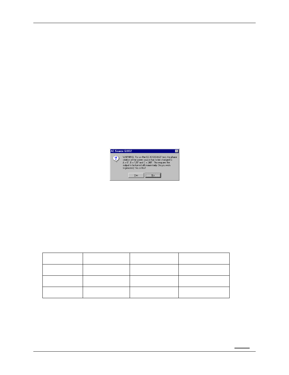
Note that the default phase rotation of the iX Series AC power systems is A = 0, B = 240 and C =
120 (counter clock wise). For the IEC 61000-4-27, the phase rotation must be set to A = 0, B =
120 and C =240. This is best done with the power to the EUT off. If the test is started and the iX
phase rotation is not A = 0, B = 120 and C =240, a warning will appear prompting the operator to
confirm the change in phase rotation. Selecting No will abort the test with no change to the source
output. Selecting Yes will result in the phase rotation being changed before the test starts. If the
phase rotation is already correct, no message appears.
11.9
Test Implementation and Test Sequence
For each test step, the specified voltage and phase angles will be applied for the time specified. At the
onset of each voltage/phase step, the source voltage is captured by the power source's data acquisition
system. Once the specified time has elapsed, the voltage and phase angles are set back to their nominal
values and the captured waveform data is transferred and displayed. This data will be visible until the next
step when it is updated. Each step (number) will be applied for a different phase rotation in the sequences
shown below. This means the operator does not have to reconnect the EUT three times using a different
phase connected at each test number.
The phase rotations used are as follows:
Sequence
First
Ua to L1
Ub to L2
Uc to L3
Second
Ua to L2
Ub to L3
Uc to L1
Third
Ua to L3
Ub to L1
Uc to L2
The test numbers executed are determined by the test selection in the main setup screen. Any
combination of test number 1, 2 and 3 may be selected by placing a check mark in the appropriate box.
11.10 Test Reports
The IEC 61000-4-27 test module produces a test report when the Print Report button is clicked or
the File, Print menu is selected. Test reports include all selected test parameters and options.
Note that IEC reports can be generated using one of three alternative methods. See the options
