Group 10 pid control parameters – Delta Electronics AC Motor Drive VFD-G User Manual
Page 68
Chapter 4 Parameters|
Revision July 2008, EG03, SW V1.06
4-17
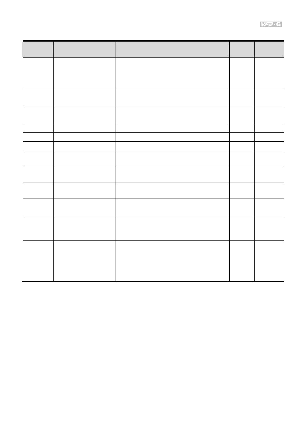
Group 10 PID Control Parameters
Parameter
Functions
Settings
Factory
Setting
Customer
10-00
Input Terminal for PID
Feedback
00: Disabled
01: Input via AI1
02: Input via AI2
03: Input via External Reference
00
10-01
PID Control Detection
Signal Reference
1.0-6550.0 1000.0
10-02
PID Feedback Control
Method
00: Normal (Err=SP-FB)
01: Inverse (Err=FB-SP)
00
10-03
Proportional Gain (P)
0.0~10.0
1.0
10-04
Integral Time (I)
0.00~100.00 Sec
1.00
10-05
Differential Time (D)
0.00~1.00 Sec
0.00
10-06 Upper
Bound
for
Integral Control
00~200% 100
10-07
Primary Low Pass
Filter Time
0.0~2.5 Sec
0.0
10-08 PID
Feedback
Signal
Range
0.01 to 10-01
600.0
10-09 PID
Feedback
Signal
Fault Treatment Time
0. 0~3600.0 Sec
0.0: Disabled
0.0
10-10 PID
Feedback
Signal
Fault Treatment
00: Warn and RAMP stop
01: Warn and COAST stop
02: Warn and keep operating
01
10-11
V/F Curve Selection
00: Determined by group 01
01: 1.5 power curve
02: 1.7 power curve
03: 2 power curve
04: 3 power curve
00