Delta Electronics AC Motor Drive VFD-G User Manual
Page 166
Appendix B Accessories|
Revision July 2008, EG03, SW V1.06
B-3
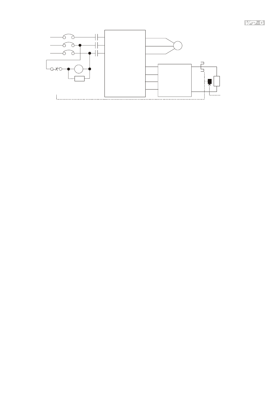
R/L1
S/L2
T/L3
NFB
MC
VFD Series
MOTOR
O.L.
U/T1
V/T2
W/T3
+ P
- N
( )
( )
B1
B2
SA
R/L1
S/L2
T/L3
MC
IM
BR
O.L.
Thermal
Overload
Relay or
temperature
switch
Surge
Absorber
Thermal Overload
Relay
Brake
Resistor
Brake
Unit
+ P
- N
( )
( )
Note1: When using the AC drive with DC reactor, please refer to wiring diagram in the AC drive
user manual for the wiring of terminal +(P) of Brake unit.
Note2:
wire terminal -(N) to the neutral point of power system.
Do NOT
Temperature
Switch
E.F
DCM
RA
RC
See also other documents in the category Delta Electronics Tools:
- SMT Power Inductor SIL104R (1 page)
- Q48SB (2 pages)
- Planar DC/DC Transformer ER/ER(Plate) 22 (1 page)
- SMT Power Inductor HCB1190B (1 page)
- Series E48SR (15 pages)
- E48SR12007 (15 pages)
- SMT Power Inductor SIWC1360 (1 page)
- PFC Chokes PFC2815V Series (1 page)
- SMT Power Inductor SIB86 (1 page)
- PMC-24V050W1AA (2 pages)
- SMT Power Inductor HCB1050 (1 page)
- SMT Power Inductor HAH1330 (1 page)
- PFC Chokes PFC4120V Series (1 page)
- PFC Choke PFC3520V Series (1 page)
- SMT Power Inductor HCB1047B (1 page)
- SMT Power Inductor HAH1365 (1 page)
- SMT Power Inductor HMS1355 (1 page)
- Series S48SA (13 pages)
- E48SC (2 pages)
- SMT Power Inductor SILM106 (1 page)
- Delphi Series L48DB (2 pages)
- S48SA (13 pages)
- E36SR (2 pages)
- 3KVA (31 pages)
- SMT Power Inductor HMU1056L (1 page)
- Through Hole Power Inductors THCBR1090 (1 page)
- SMT Power Inductor SIL625 (1 page)
- SMT Power Inductor 1378(S) (1 page)
- Through Hole Power Inductors 1411 (1 page)
- Current Sense Transformers TCE1310H (1 page)
- H48SR (13 pages)
- Series E48SH (15 pages)
- AC Motor Drive VFD-EL (209 pages)
- Through Hole Power Inductors THAH1095 (1 page)
- Suppression Inductors LFU09V (1 page)
- SMT Power Inductor HCB0740A (1 page)
- Power Output Module DVPPS01 (2 pages)
- SMT Power Inductor SIR74 (1 page)
- L36SA (2 pages)
- 4.5V~ 5.5V (3 pages)
- Delphi Series V48SB (2 pages)
- Series S48SP (14 pages)
- Series 240W (11 pages)
- Delphi Series E24SR (15 pages)