Delta Electronics AC Motor Drive VFD-G User Manual
Page 57
Chapter 4 Parameters|
4-6
Revision July 2008, EG03, SW V1.06
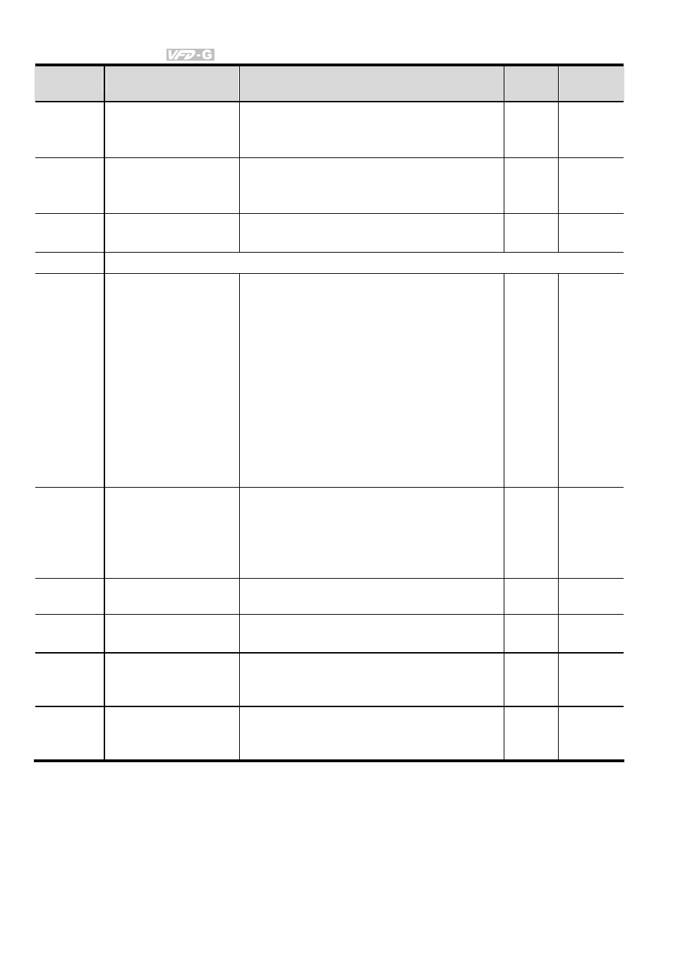
Parameter
Functions
Settings
Factory
Setting
Customer
02-04 Forward/Reverse
Enable
00: Forward enabled
01: Reverse disabled
02: Forward disabled
00
02-05 2-wire/3-wire
Operation Control
Modes
00: 2-wire: FWD/STOP, REV/STOP
01: 2-wire: FWD/REV, RUN/STOP
02: 3-wire operation
00
02-06
Line Start Lockout
00: Disabled
01: Enabled
01
02-07 Reserved
02-08 Start-up
Display
Selection
Bit0~1: 00 = F LED
01 = H LED
10 = U LED (special display)
11 = Fwd / Rev
Bit2: 0 = Fwd LED /
1 = Rev LED
Bit3~5: 000 = 1st 7-step
001 = 2nd 7-step
010 = 3rd 7-step
011 = 4th 7-step
100 = 5th 7-step
Bit6~7: Reserved
00
02-09 Special Display
00: A displays output current of AC drive
01: U displays DC-Bus voltage of AC drive
02: E displays RMS of output voltage
03: P displays feedback Signal
04: PLC display auto procedure state
00
02-10 User
Defined
Coefficient
0.01~160.00
1.00
02-11 Flying Start
00: Disabled
01: Enable (Dc braking disabled)
00
02-12 Flying
Start
Frequency
00: Trace from master frequency command
01: Trace from maximum setting frequency
01-00
00
02-13 Master
Frequency
Memory Setting
00: Do not remember the last known
frequency
01: Remember the last known frequency
01