Dc braking time – Delta Electronics AC Motor Drive VFD-G User Manual
Page 114
Chapter 4 Parameters|
Revision July 2008, EG03, SW V1.06
4-63
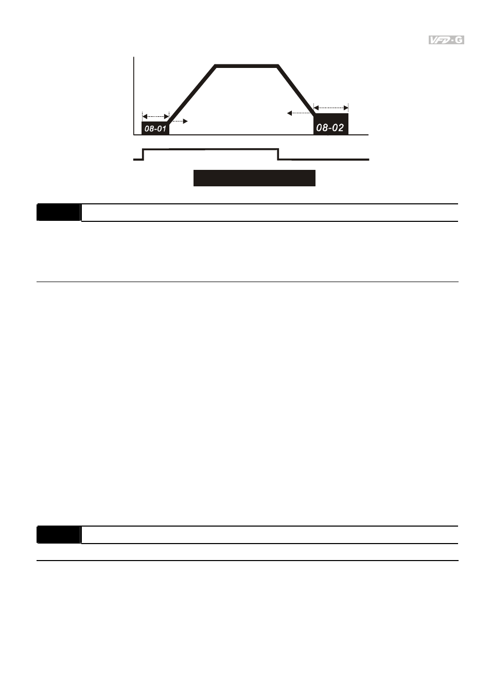
Output frequency
Time
DC Braking Time
ON
OFF
Run/Stop
DC braking
current
level
DC braking
time during
stopping
Minimum
output
frequency
Stop point for
DC braking
time during
stopping
01-05
08-03
08 - 04
Momentary Power Loss Operation Selection
Factory Setting: 00
Settings
00:
Disabled
01: Trace from top downward
02: Trace from bottom upward
This parameter determines the start-up mode after momentary power loss operation.
The power system connects to AC drive may occurred momentary power loss by any probably
reason. This function can make AC drive output voltage continuously after power loss and AC
drive won’t stop by power loss.
If this parameter is set to 01, AC drive will trace from the last frequency before power loss
downward. After output frequency of AC drive and running speed of the motor is
synchronization, it will accelerate to master frequency command. It is recommended to use
this setting if the motor loading has the characteristics of high inertial and low resistance.
If this parameter is set to 02, AC drive will trace from the Min. frequency upward. After output
frequency of AC drive and running speed of the motor is synchronization, it will accelerate to
master frequency command. It is recommended to use this setting if the motor loading has the
characteristics of low inertial and high resistance.
08 - 05
Maximum Allowable Power Loss Time
Unit: 0.1
Settings
0.1~5.0 Sec
Factory Setting: 2.0
This parameter determines the maximum allowable power loss time. If the power loss time is
less than the time defined by this parameter, the AC drive will execute 08-04 momentary
power loss operation.
The allowable power loss time is beginning to count time after AC drive displays Lu. Therefore,
actual allowable power loss time will change with loading.