3 main circuit connection, 3 main circuit connection -3, Im 3 – Delta Electronics AC Motor Drive VFD-G User Manual
Page 31: Vfd-g
Chapter 2 Installation and Wiring|
2-8
Revision July 2008, EG03, SW V1.06
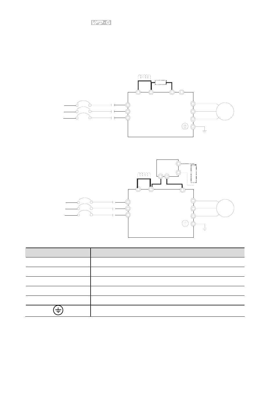
2.3 Main Circuit Connection
+1 +2/B1
-
Jumper
DC Reactor
(O pti onal)
B2
BR
Br ak e Resistor
(O pti onal)
For 460V series, 20hp and below
R/L1
S/L2
T /L3
U/T1
V/T2
W/T 3
IM
3~
Motor
MC
VFD-G
NFB
NFB
R/L1
S/L2
T /L3
R/L1
S/L2
T /L3
+1
+2
-
U/T1
V/T2
W/T3
IM
3~
Motor
MC
VFD-G
Jumper
DC Reactor
(O pti onal)
Br ak e
Resistor
(O pti onal)
P N
B1
B2
VFDB
Br ak e
Unit (O pti onal)
NFB
NFB
R/L1
S/L2
T /L3
For 460V series, 25hp and above
Terminal Symbol
Explanation of Terminal Function
R/L1, S/L2, T/L3
AC line input terminals
U/T1, V/T2, W/T3
AC drive output terminals motor connections
+1, +2
Connections for DC Link Reactor (optional)
+2/B1~B2
Connections for Braking Resistor (optional)
+2~ -, +2/B1~ -
Connections for External Braking Unit (VFDB series)
Earth Ground
- SMT Power Inductor SIL104R (1 page)
- Q48SB (2 pages)
- Planar DC/DC Transformer ER/ER(Plate) 22 (1 page)
- SMT Power Inductor HCB1190B (1 page)
- Series E48SR (15 pages)
- E48SR12007 (15 pages)
- SMT Power Inductor SIWC1360 (1 page)
- PFC Chokes PFC2815V Series (1 page)
- SMT Power Inductor SIB86 (1 page)
- PMC-24V050W1AA (2 pages)
- SMT Power Inductor HCB1050 (1 page)
- SMT Power Inductor HAH1330 (1 page)
- PFC Chokes PFC4120V Series (1 page)
- PFC Choke PFC3520V Series (1 page)
- SMT Power Inductor HCB1047B (1 page)
- SMT Power Inductor HAH1365 (1 page)
- SMT Power Inductor HMS1355 (1 page)
- Series S48SA (13 pages)
- E48SC (2 pages)
- SMT Power Inductor SILM106 (1 page)
- Delphi Series L48DB (2 pages)
- S48SA (13 pages)
- E36SR (2 pages)
- 3KVA (31 pages)
- SMT Power Inductor HMU1056L (1 page)
- Through Hole Power Inductors THCBR1090 (1 page)
- SMT Power Inductor SIL625 (1 page)
- SMT Power Inductor 1378(S) (1 page)
- Through Hole Power Inductors 1411 (1 page)
- Current Sense Transformers TCE1310H (1 page)
- H48SR (13 pages)
- Series E48SH (15 pages)
- AC Motor Drive VFD-EL (209 pages)
- Through Hole Power Inductors THAH1095 (1 page)
- Suppression Inductors LFU09V (1 page)
- SMT Power Inductor HCB0740A (1 page)
- Power Output Module DVPPS01 (2 pages)
- SMT Power Inductor SIR74 (1 page)
- L36SA (2 pages)
- 4.5V~ 5.5V (3 pages)
- Delphi Series V48SB (2 pages)
- Series S48SP (14 pages)
- Series 240W (11 pages)
- Delphi Series E24SR (15 pages)