Delta Electronics AC Motor Drive VFD-G User Manual
Page 33
Chapter 2 Installation and Wiring|
2-10
Revision July 2008, EG03, SW V1.06
To improve the power factor and reduce harmonics, connect a DC reactor between terminals [+1,
+2(+2/B1)]. Please remove the jumper before connecting the DC reactor.
Models of 18.5kW~160kW have a built-in DC reactor; models of 185kW~220kW have a built-in
AC reactor.
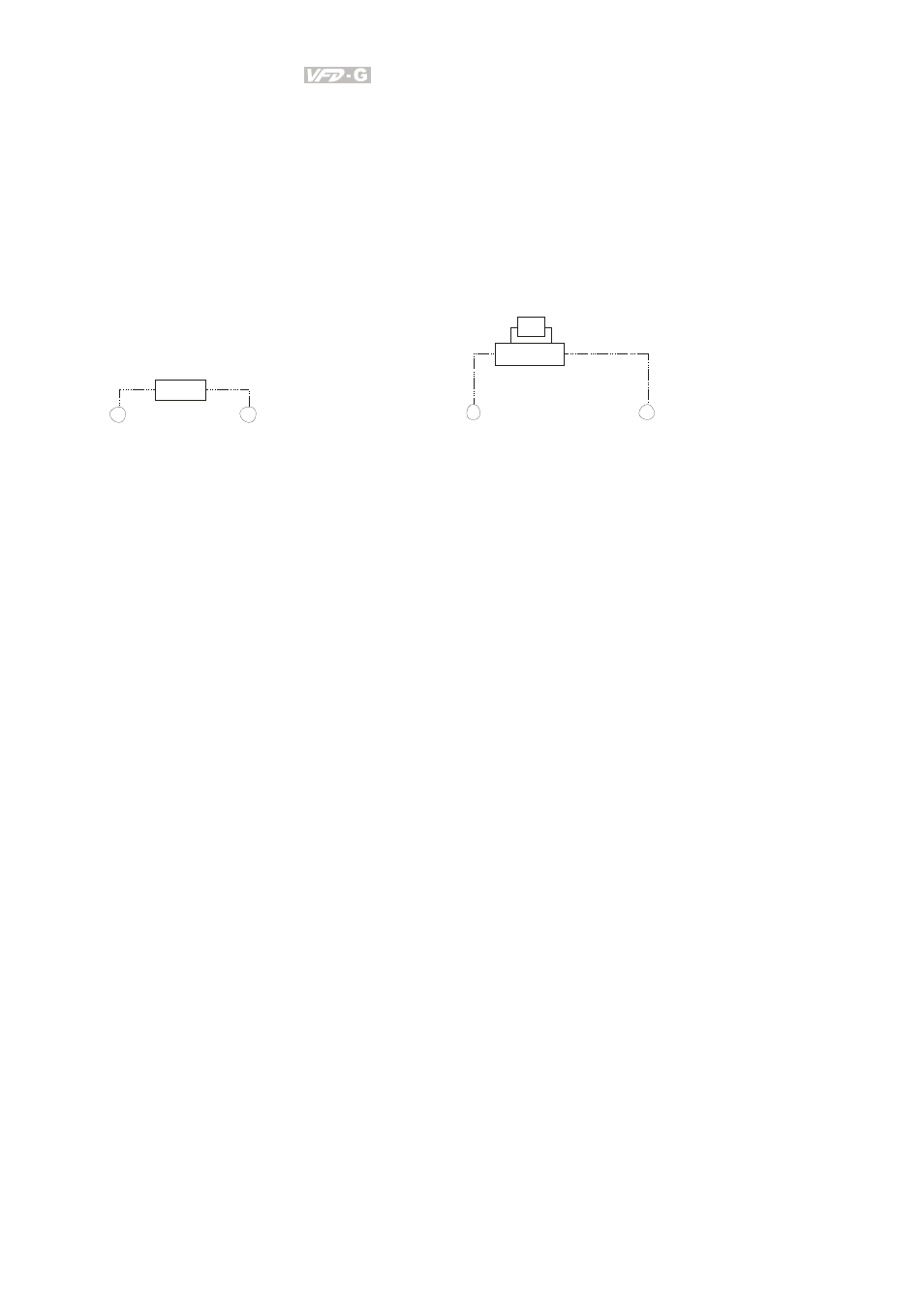
Terminals [+2/B1, B2] for connecting brake resistor and terminals [+2(+2/B1), -] for connecting
external brake unit
+2/B1
B2
B R
Bra ke Resistor (Opt io nal)
Ref er to Appen dix B for details.
Fo r 460V series, 20H P and below
+2
-
VFDB
BR
Bra ke Resistor/Unit (Opt ional)
Ref er to App endix B f or deta ils.
Fo r 460V series, 25HP an d abo ve
Connect a brake resistor or brake unit in applications with frequent deceleration ramps, short
deceleration time, too low brake torque or requiring increased brake torque.
If the AC motor drive has a built-in brake chopper (all models of 15kW and below), connect the
external brake resistor to the terminals [+2/B1, B2].
Models of 18.5kW and above don’t have a built-in brake chopper. Please connect an external
optional brake unit (VFDB-series) and brake resistor. Refer to VFDB series user manual for
details.
When not used, please leave the terminals [+2(+2/B1), -] open.
Short-circuiting [B2] or [-] to [+2/B1] can damage the AC motor drive.
Connect the terminals [+(P), -(N)] of the brake unit to the AC motor drive terminals
[+2(+2/B1), -]. The length of wiring should be less than 5m with twisted cable.