Group 4 input function parameters – Delta Electronics AC Motor Drive VFD-G User Manual
Page 59
Chapter 4 Parameters|
4-8
Revision July 2008, EG03, SW V1.06
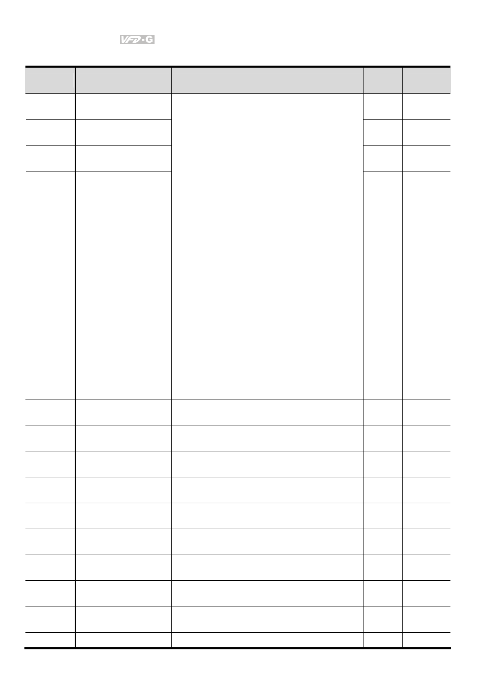
Group 4 Input Function Parameters
Parameter
Functions
Settings
Factory
Setting
Customer
04-00 Multi-function
Input
Terminal 1
01
04-01 Multi-function
Input
Terminal 2
02
04-02 Multi-function
Input
Terminal 3
03
04-03 Multi-function
Input
Terminal 4
00: disabled
01: Multi-Speed terminal 1
02: Multi-Speed terminal 2
03: Multi-Speed terminal 3
04: Multi-Speed terminal 4
05: Reset (NO)
06: Reset (NC)
07: Jog operation (JOG)
08: Accel/Decel disabled
09: 1st and 2nd Accel/Decel selection
10: 3rd and 4th Accel/Decel selection
11: B.B. (NO) input
12: B.B. (NC) input
13: Increase Frequency
14: Decrease Frequency
15: Emergency stop (NO)
16: Emergency stop (NC)
17: KEYPAD(open), EXT(close)
18: PID disable
19: Run PLC Program
20: Pause PLC Program
21: 1st Output Frequency Gain (Pr.04-30)
22: 2nd Output Frequency Gain (Pr.04-31)
23: 3rd Output Frequency Gain (Pr.04-32)
04
04-04 Digital
Input
Terminal
Response Time
01~20 01
04-05
Minimum AI1 Analog
Input
0 ~ 100%
0
04-06
Maximum AI1 Analog
Input
0 ~ 100%
100
04-07
Minimum Output that
corresponds to AI1
0.00~100.00%
0.00
04-08 Maximum
Output
that
corresponds to AI1
0.00~100.00%
100.00
04-09
Minimum AI2 Analog
Input
0 ~ 100%
0
04-10
Maximum AI2 Analog
Input
0 ~ 100%
100
04-11
Minimum Output that
corresponds to AI2
0.0~100.0%
0.00
04-12 Maximum
Output
that
corresponds to AI2
0.0~100.0%
100.00
04-13 1st
AI1
Gain
0.0~100.0%
100.0