Sensor head unit, Sensor head unit -8 – KEYENCE IL Series User Manual
Page 20
1-2 Part Names and Functions
1-8
1
Bef
ore Use
IL-E
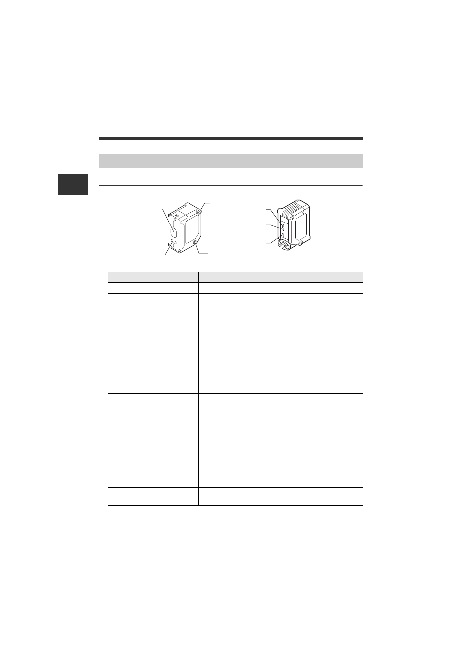
IL-S025/IL-030/IL-S065/IL-065/IL-100/IL-300/IL-600/IL-2000
Sensor Head Unit
Item
Description
(1) Laser receiver
Laser receiver port. The surface is covered with glass.
(2) Laser transmitter
Laser emission port. The surface is covered with glass.
(3) Mounting section
Screwed onto dedicated bracket, etc.
(4) Reference distance
indicator
By default (normal display mode), and "17. Head Display
Mode" (page 4-40), the reference distance indicator lights
within the following detection range.
• IL-S025: 25 mm ± 0.25 mm
• IL-030: 30 mm ± 0.25 mm
• IL-S065/IL-065: 65 mm ± 0.5 mm
• IL-100: 100 mm ± 1 mm
• IL-300: 300 mm ± 7 mm
• IL-600: 600 mm ± 20 mm
• IL-2000: 2000 mm ± 50 mm
(5) Analog range indicator
By default (normal display mode), the analog range indicator
lights when the P.V. (judgment value) is within analog output
range. The indicator lights within the following detection
range, when the analog output setting is OFF and with the
expansion units.
• IL-S025: 25 mm ± 5 mm
• IL-030: 30 mm ± 5 mm
• IL-S065/IL-065: 65 mm ± 10 mm
• IL-100: 100 mm ± 20 mm
• IL-300: 300 mm ± 140 mm
• IL-600: 600 mm ± 400 mm
• IL-2000: 2000 ± 1000 mm
(6) Laser warning emission
indicator
Lights up while the laser beam is being emitted.
Blinks while the laser beam emission is stopped.
IL-030
CENTER
A. RANGE
LASER
(1)
(2)
(3)
(3)
(4)
(5)
(6)