Pqw, 5*k(6, E/.qe – KEYENCE IL Series User Manual
Page 132: Append ix il-e, Display description corrective actions
A-6
Append
ix
IL-E
The internal
measurement value
(R.V.) is displayed
as [-ffff].
The internal measurement
value (R.V.) falls below the
lower limit (-99.999) of display
range.
• Check the setting for shift target value and shift
the display again.
“3-5 Zero Shift Function (Shifting the
Internal Measurement Value (R.V.))”
• Redo the calibration.
“Calibration Function” (page 4-45)
The internal
measurement value
(R.V.) is displayed
as [ffff].
The internal measurement
value (R.V.) goes beyond the
upper limit (99.999) of display
range.
The bank switching method is
set to external input.
To switch the banks with button operations, set
“12. Bank switching method” to [btn].
When the R.V. (Internal
Measurement Value) is
[-----], the tolerance tuning
and the 2 point tuning will
occur, and, when the P.V.
(Judgment Value) is [-----] 1
point tuning will occur.
When the internal measurement value (R.V.) and
judgment value (P.V.) is a number value, conduct
tuning by the condition of the measured
measurement object.
“Setting the Tolerance Setting Value” (page 3-10)
• When the R.V. is [-----],
the zero shift function was
used.
• When the “3.AVE” is [HPF],
the zero-shift was used.
• Shift the display when the internal
measurement value (R.V.) is displayed (with
the object measured).
“Zero Shift Function (Shifting the Internal
Measurement Value (R.V.))” (page 3-18)
• Make sure the “3.AVE” is not [HPF].
“3. Averaging rate, Step count filter,
The SET1, SET2, or SET3 value
is incorrect and the correction
using the calibration function
could not be performed.
Perform the calibration within the possible
correction range.
“Calibration Function” (page 4-45)
The button operation is
disabled.
The connected communication unit
read/write setting switch is set to RW.
Set the read/write setting switch to R.
"RS-232C Communication Unit DL-RS1A
User's Manual"
The light amount is saturated.
Tilt the sensor head so that regular reflectance
beam is not received.
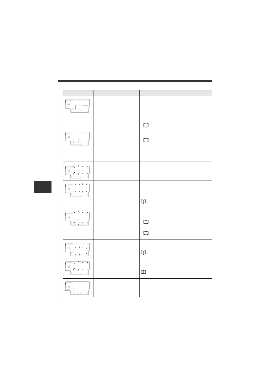
Display
Description
Corrective actions
((((
LASER
BANK
0
1
2
3
HI
LO
R.V.
ANALOG
HI
SHIFT
ZERO SHIFT
TIMING
LO
ALIGNMENT
((((
HOLD
CALC
CHECK
GO
((((
LASER
BANK
0
1
2
3
HI
LO
R.V.
ANALOG
HI
SHIFT
ZERO SHIFT
TIMING
LO
ALIGNMENT
((((
HOLD
CALC
CHECK
GO
LASER
BANK
0
1
2
3
HI
LO
R.V.
ANALOG
HI
SHIFT
ZERO SHIFT
TIMING
LO
GO
HOLD
CALC
CHECK
$-.QE
LASER
BANK
0
1
2
3
HI
LO
R.V.
ANALOG
HI
SHIFT
ZERO SHIFT
TIMING
LO
ALIGNMENT
PQW#.
GO
HOLD
CALC
CHECK
'TT
LASER
BANK
0
1
2
3
HI
LO
R.V.
ANALOG
HI
SHIFT
ZERO SHIFT
TIMING
LO
ALIGNMENT
5*K(6
GO
HOLD
CALC
CHECK
'TT
LASER
BANK
0
1
2
3
HI
LO
R.V. ANALOG
HI SHIFT
ZERO SHIFT
TIMING
LO
ALIGNMENT
5'6
GO
HOLD CALC CHECK
LASER
BANK
0
1
2
3
HI
LO
R.V.
ANALOG
HI
SHIFT
ZERO SHIFT
TIMING
LO
ALIGNMENT
E/.QE
GO
HOLD
CALC
CHECK
LASER
BANK
0
1
2
3
HI
LO
R.V.
ANALOG
HI
SHIFT
ZERO SHIFT
TIMING
LO
GO
HOLD
CALC
CHECK
WWWWW