Rockwell Automation 1336S Plus FRN 1.xx-5.xx User Manual
Page 43
2–33
Installation/Wiring
The interface board is jumper selectable to accept a 5V TTL or 12V
DC square-wave with a minimum high state voltage of 3.0V DC
(TTL) or 7.0V DC (12 volt encoder). Maximum low state voltage is
0.4V DC. Recommended wire – shielded, 0.750 mm
2
(18 AWG),
305 m (1000 ft.) or less. Maximum input frequency is 125kHz. See
Encoder & Communications Cabling on page 2–9.
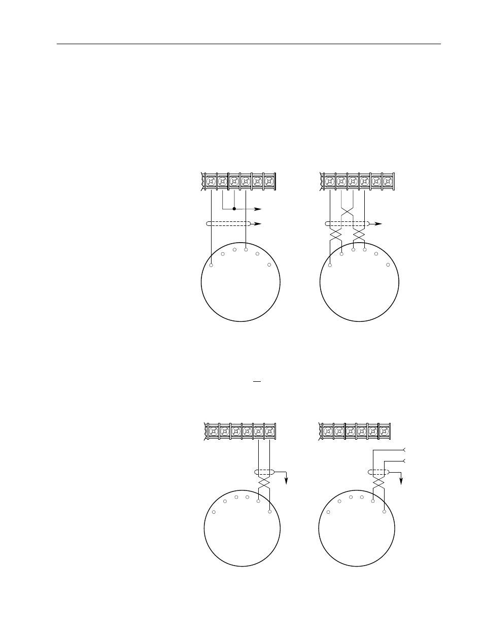
Figure 2.6 d
Encoder Signal Wiring
31
Single-Ended, Dual-Channel
1
Differential
Single-Ended
Encoder Output
Connections
Differential
Encoder Output
Connections
32
33
34
35
36
A
B NOT
A NOT
B
31
TB3
32
33
34
35
36
to TE
A
B NOT
A NOT
B
TB3
to TE
to
Power Supply Common
(Terminal 36 or External)
1
For Single-Ended, Single-Channel (pulse) applications, eliminate the B and B (NOT) connections.
Some encoders may label the "A" connection as "Signal."
Important:
Correct direction of motor rotation as determined
during start-up (see Chapter 4) may require that the
A or B channel wiring be reversed.
Figure 2.6 e
Encoder Power Wiring
Common
+12V DC
(200 mA)
31
TB3
to TE
Internal
External
Encoder Power
Connections
using 12V DC Internal
(Drive) Power Source
Encoder Power
Connections using
External DC
Power Source
32
33
34
35
36
+
Common
External
Power
Supply
31
TB3
32
33
34
35
36
Important: Control Interface Board jumpers JP3 & JP4 must be set for the voltage level of the encoder output.
Minimum On Volts = 7V DC
Minimum Current = 10mA
Minimum On Volts = 3V DC
Minimum Current = 10mA
to TE