Rockwell Automation 1336S Plus FRN 1.xx-5.xx User Manual
Page 38
2–28
Installation/Wiring
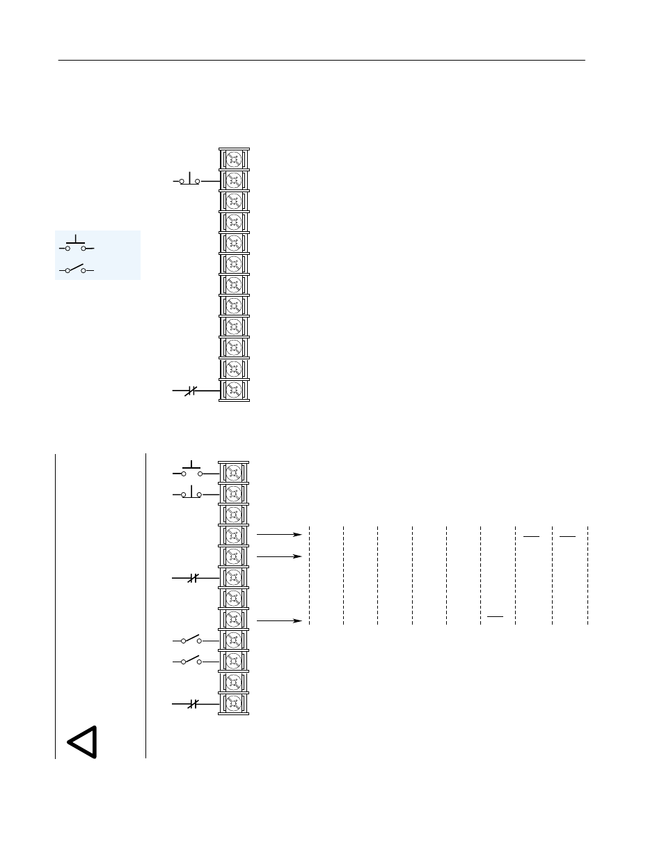
Figure 2.5
Input Mode Selection & Typical TB3 Connections
19
20
21
22
23
24
25
26
27
28
29
30
Status
Stop/Fault Reset
3
Common
Status
Status
Status
Common
Status
Status
Status
Common
Enable
3
[Input Mode] 1
Factory Default
19
20
21
22
23
24
25
26
27
28
29
30
Start
Stop/Fault Reset
3
Common
Auxiliary
3
Common
Speed Select 2
1
Speed Select 1
1
Common
Enable
3
Jog
7
Stop
Type
2nd
Accel
Digital
Pot Up
Jog
7
Reverse
4
Reverse
4
Reverse
4
Reverse
4
Reverse
4
Reverse
4
Integrator
Reset
6
Speed
Select 3
1
Speed
Select 3
1
2nd
Decel
Digital
Pot Dn
Local
Control
2
Jog
7
Jog
7
Integrator
Reset
6
Speed
Select 3
1
2
3
4
5
6
17
5
18
5
Integrator
Reset
6
PI
Output
Speed
Select 3
1
22
8
Mode
[Input Mode] 2-6, 17, 18, 22
Three-Wire Control with Single-Source Reversing
See Figure 2.6 for Wiring Information
See Figure 2.6 for Wiring Information
ATTENTION:
The JOG function will not operate properly
unless a SCANport option is connected to the drive. To assure
proper JOG function, install at least one of the following:
1201-HAP, 1201-HA1, 1201-HA2, 1336-GM1. Applies to
1305 with firmware FRN 2.01 or earlier and 1336 PLUS with
Language Module 1336S-EN firmware FRN 1.05 or earlier.
!
Note: If this mode is selected, the status of all
inputs can be read at the [Input Status] parameter.
However, only “Stop/Fault Reset” and “Enable” will
have control function.
1
See Speed Select Table.
2
Drive must be stopped to take Local Control. Control by all other
adapters is disabled (except Stop).
3
These inputs must be present before drive will start.
4
Bit 0 of [Direction Mask] must = 1 to allow TB3 direction change.
5
Firmware version 3.01 and Up, Only.
6
Inverted function – voltage resets integrator to zero.
7
See ATTENTION statement on this page.
8
Firmware version 4.01 and Up, Only.
Momentary
Maintained