Typical serial communications configurations, Without block transfer – Rockwell Automation 1336S Plus FRN 1.xx-5.xx User Manual
Page 155
A–15
Specifications and Supplemental Information
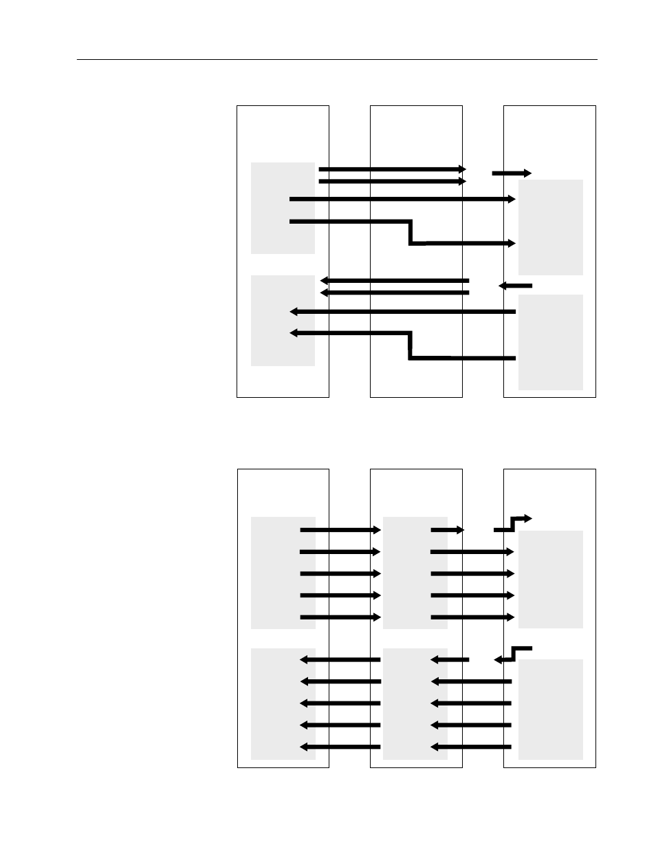
Without Block Transfer
1
Programmable
Controller
I/O Image Table
Remote I/O
Communication
Module
1336 PLUS
Adjustable Frequency
AC Drive
Logic Command
Analog Reference
WORD 2
WORD 3
WORD 4
WORD 5
WORD 6
WORD 7
Output Image
Datalink A
Datalink C
Datalink A
Datalink C
Data In A1
Data In A2
Data In B1
Data In B2
Data In C1
Data In C2
Data In D1
Data In D2
111
112
113
114
115
116
117
118
Parameter/Number
Data Out A1
Data Out A2
Data Out B1
Data Out B2
Data Out C1
Data Out C2
Data Out D1
Data Out D2
119
120
121
122
123
124
125
126
Parameter/Number
Direct
to
Drive
Logic
Direct
from
Drive
Logic
Logic Status
Analog Feedback
WORD 2
WORD 3
WORD 4
WORD 5
WORD 6
WORD 7
Input Image
1
Refer to the 1203 User Manual for further information.
Master Device
Register Objects
Serial to SCANport
Communications Module
1336 PLUS
Adjustable Frequency
AC Drive
WORD 1
WORD 2
WORD 3
WORD 4
WORD 5
WORD 6
WORD 7
WORD 8
WORD 9
WORD 10
WORD 1
WORD 2
WORD 3
WORD 4
WORD 5
WORD 6
WORD 7
WORD 8
WORD 9
WORD 10
Output
WORD 1
WORD 2
WORD a
WORD a+1
WORD b
WORD b+1
WORD c
WORD c+1
WORD d
WORD d+1
WORD 1
WORD 2
WORD a
WORD a+1
WORD b
WORD b+1
WORD c
WORD c+1
WORD d
WORD d+1
Output
Datalink C
Datalink D
Datalink A
Datalink B
Datalink C
Datalink D
Datalink A
Datalink B
Data In A1
Data In A2
Data In B1
Data In B2
Data In C1
Data In C2
Data In D1
Data In D2
111
112
113
114
115
116
117
118
Parameter/Number
Data Out A1
Data Out A2
Data Out B1
Data Out B2
Data Out C1
Data Out C2
Data Out D1
Data Out D2
119
120
121
122
123
124
125
126
Parameter/Number
Direct
to
Drive
Logic
Direct
from
Drive
Logic
Input
Input
Typical Serial
Communications
Configurations