Power cabling – Rockwell Automation 1336S Plus FRN 1.xx-5.xx User Manual
Page 21
2–11
Installation/Wiring
Input and output power connections are performed through terminal
block, TB1 (see Figure 2.1 for location).
Important:
For maintenance and setup procedures, the drive may
be operated without a motor connected.
Table 2.B
TB1 Signals
Terminal
Description
PE
Potential Earth Ground
TE
Shield Termination – True Earth
R (L1), S (L2), T (L3)
AC Line Input Terminals
+DC, –DC
DC Bus Terminals
U (T1), V (T2), W (T3)
Motor Connection
!
ATTENTION: The National Codes and standards
(NEC, VDE, BSI etc.) and local codes outline
provisions for safely installing electrical equipment.
Installation must comply with specifications regarding
wire types, conductor sizes, branch circuit protection
and disconnect devices. Failure to do so may result in
personal injury and/or equipment damage.
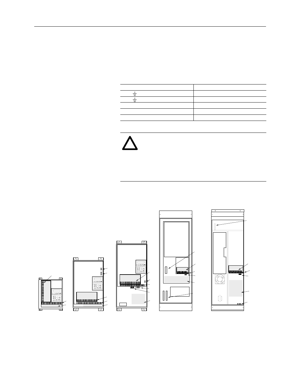
Figure 2.1
Terminal Block Locations
TB1
TB2
TB3
TB3
TB1
TB2
TB4
TB6
Power Terminal Block
Control & Signal Wiring
Control Interface Option
24V DC Auxiliary Input
High Voltage DC Auxiliary Input
480 or 600V Auxiliary Output (F Frame Only)
Shield Terminals
TB1
TB2
TB3
TB4
TB6
TB9
TE
Frames B, C
1
Frames D, E
1
Frames A1-A4
1
TB1
TB2
TB3
Control Interface
Option
Control Interface
Option
TB1
TB1
TB1
Location
TB1 Location
Control Interface
Option
TB4
TB6
TE
1
Refer to page 1–1 for frame reference classifications and Figure 2.2 for TB1 details.
TB1
Frame G
1
Frame F
1
U, V, W
& Brake
Terminals
TB2
TB3
Brake
Terminals
R, S, T
TE
TE
PE
Ground
TB2
TB3
TB9
TB1
Location
Power Cabling