SATEC PM180 Operation Manual User Manual
Page 88
Chapter 8 Configuring Recorders
Configuring the Data Recorder
86
PM180 Substation Automation Unit
No
.
Parameter
No. Parameter
5
RT (1-cycle) I2
13
RT (1-cycle) V3 THD
6
RT (1-cycle) I3
14
RT (1-cycle) I1 THD
7
RT (1-cycle) Total kW
15
RT (1-cycle) I2 THD
8
RT (1-cycle) Total kvar
16
RT (1-cycle) I3 THD
Data Log #2
1
kW Import Sliding Demand
9
I1 Demand
2
kvar Import Sliding Demand
10
I2 Demand
3
KVA Sliding Demand
11
I3 Demand
4
kWh Import
12
V1 Demand
5
kWh Export
13
V2 Demand
6
kvarh Import
14
V3 Demand
7
kvarh Export
15
RT (1-cycle) I4
8
kVAh
16
RT (1-cycle) V4
Setpoint #1 is preset at the factory to trigger Data logs #1 and #2 in 15 min intervals.
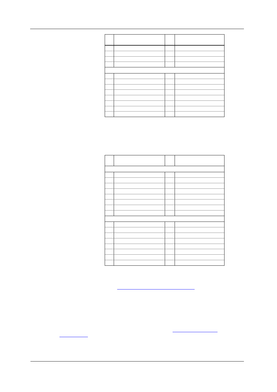
Factory Preset Fault and PQ Data Logs
Data logs #13 and #14 are factory preset for RMS trending on the fault and power
quality events and are intended for the use with the Fault and PQ recorders. The
default PQ and Fault data log configuration is shown in the following table.
No
.
Parameter
No. Parameter
Data Log #13 (fault data trend)
1
Generic V1
9
Generic V ZERO-SEQ
2
Generic V2
10
Generic VDC
3
Generic V3
4
Generic V4
5
Generic I1x
6
Generic I2x
7
Generic I3x
8
Generic I4x
Data Log #14 (PQ data trend)
1
Generic V1
9
Generic FREQ
2
Generic V2
3
Generic V3
4
Generic V4
5
Generic I1x
6
Generic I2x
7
Generic I3x
8
Generic I4x
The generic data group represents generic volts, amps, etc., regardless of the data
integration time. The PQ recorder can use different time envelopes to record data
integrated over intervals from a half cycle to 10 minutes depending on the duration of
the power quality event (see
Configuring the Power Quality Recorder
). The Fault
recorder uses only the half-cycle RMS trend.
TOU Profile Data Log Files
Data log files #15 and #16 are configurable to store the TOU monthly profile log and
the TOU daily profile log respectively.
A TOU profile log file is organized as a multi-section file that has a separate section
for each TOU energy and maximum demand register. The number of sections is
taken automatically from the Summary/TOU Registers setup (see
in Chapter 9). Since each TOU energy register has a shadow
maximum demand register, the number of sections in the file is twice the number of
the allocated TOU registers.