Common measurements display – SATEC PM180 Operation Manual User Manual
Page 30
Chapter 3 Using the RDM
Data Display
28
PM180 Substation Automation Unit
Pressing both the UP and DOWN arrow keys together returns to the first page within
the current display.
The common measurements display (main screen) does not have an indicator LED.
If no LED is lit up below the display, this means that the common measurement
parameters are being displayed at this time. To return to the common measurements
from another display, just press the same key (the key pointed to by an illuminated
LED) until the illuminated LED goes out.
Common Measurements Display
The RDM is displaying the common measurements parameters if none of the display
LEDs are illuminated. Press the key indicated by the illuminated LED to return to the
common measurements parameters.
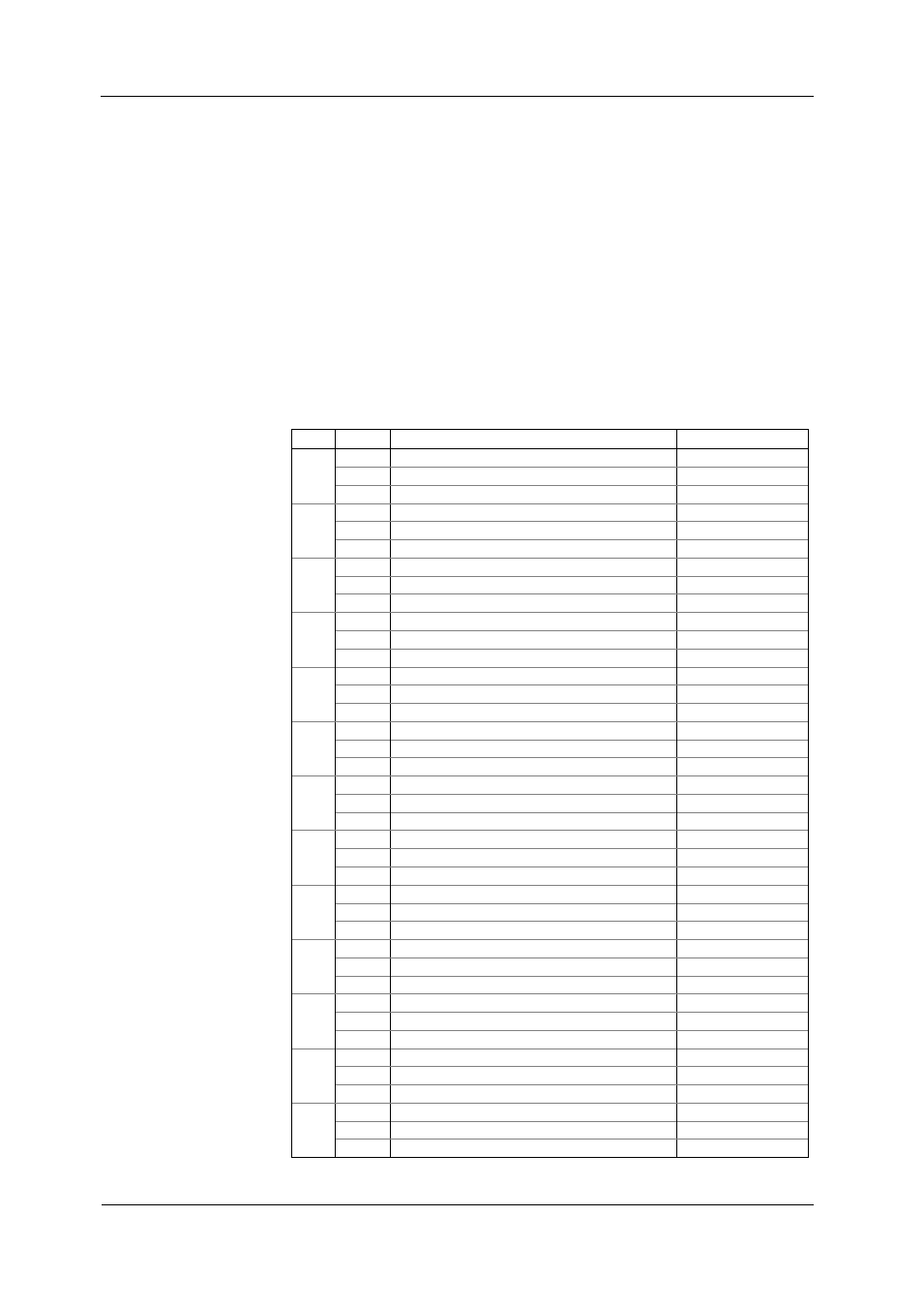
The following table shows common measurements pages displayed. The bold font
highlights the abbreviated labels that appear in the windows to designate some
parameters in addition to the LEDs that show measurement units. Note that phase-
to-
neutral volts page (with the “P” label) is displayed only in wiring connections with a
neutral.
Page Label
Parameter
Units LED
1
V12
V1/V1-2 - kV1/kV1-2
V23
V2/V2-3 - kV2/kV2-3
L
V31
V3/V3-1 - kV3/kV3-1
2
V1
V1/V1-2 - kV1/kV1-2
V2
V2/V2-3 - kV2/kV2-3
P
V3
V3/V3-1 - kV3/kV3-1
3
I1
A1
I2
A2
I3
A3
4
Total kVA
kVA/MVA
Total power factor
PF
Total kW
kW/MW
5
Neutral current
A Neut.
Frequency
Hz
Total kvar
kvar/Mvar
6
C4
I4
7
U. dC.
DC voltage
8
U. Unb.
Voltage unbalance
9
C. Unb.
Current unbalance
10
Ph.L1
Power factor L1
PF
kW L1
kW/MW
11
kVA L1
kVA/MVA
Ph.L1
kvar L1
kvar/Mvar
12
Ph.L2
Power factor L2
PF
kW L2
kW/MW
13
kVA L2
kVA/MVA
Ph.L2
kvar L2
kvar/Mvar