Appendix a parameters for analog output – SATEC PM180 Operation Manual User Manual
Page 155
Appendix A Parameters for Analog Output
PM180 Substation Automation Unit
153
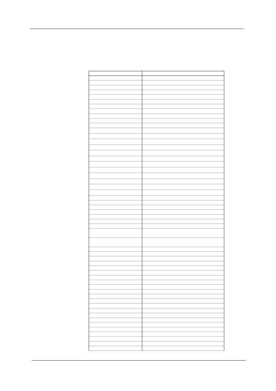
Appendix A Parameters for Analog Output
The following table lists parameters that can be provided on the
device’s analog outputs.
Designation
Description
NONE
None (output disabled)
1-Cycle Phase Values
V1 RT
V1 Voltage
V2 RT
V2 Voltage
V3 RT
V3 Voltage
V12 RT
V12 Voltage
V23 RT
V23 Voltage
V31 RT
V31 Voltage
I1 RT
I1 Current
I2 RT
I2 Current
I3 RT
I3 Current
V1 THD RT
V1 Voltage THD
V2 THD RT
V2 Voltage THD
V3 THD RT
V3 Voltage THD
I1 THD RT
I1 Current THD
I2 THD RT
I2 Current THD
I3 THD RT
I3 Current THD
I1 TDD RT
I1 Current TDD
I2 TDD RT
I2 Current TDD
I3 TDD RT
I3 Current TDD
I1 KF RT
I1 K-Factor
I2 KF RT
I2 K-Factor
I3 KF RT
I3 K-Factor
1-Cycle Total Values
kW RT
Total kW
kvar RT
Total kvar
kVA RT
Total kVA
PF RT
Total PF
PF LAG RT
Total PF Lag
PF LEAD RT
Total PF Lead
VOLT AVG RT
3-phase
average
L-N/L-L
voltage
VOLT AVG LL
RT
3-phase average L-L voltage
AMPS AVG RT
3-phase average current
1-Cycle Auxiliary Values
I4 RT
I4 Current
In RT
In Current
FREQ RT
Frequency
VOLT DC RT
DC voltage
1-Sec Phase Values
V1 AVR
V1 Voltage
V2 AVR
V2 Voltage
V3 AVR
V3 Voltage
V12 AVR
V12 Voltage
V23 AVR
V23 Voltage
V31 AVR
V31 Voltage
I1 AVR
I1 Current
I2 AVR
I2 Current
I3 AVR
I3 Current
1-Sec Total Values
kW AVR
Total kW
kvar AVR
Total kvar
kVA AVR
Total kVA
PF AVR
Total PF
PF LAG AVR
Total PF Lag